Centralized electric lapping module and electric lapping network

A kind of electrical overlapping and centralized technology, applied in the direction of transportation and packaging, aircraft parts, etc., can solve the problems of poor electromagnetic environment, messy wiring harness laying, increasing the difficulty of electromagnetic compatibility design, etc., to reduce design difficulty and cost, easy maintenance effect

Inactive Publication Date: 2013-09-04
R&D INST OF CHINA AVIATION IND GENERAL AIRCRAFT
View PDF6 Cites 0 Cited by
  • Summary
  • Abstract
  • Description
  • Claims
  • Application Information

AI Technical Summary

Problems solved by technology

For the negative line return lap, if the existing equipment positive and negative two-wire design is adopted, the negative line cable harness is too thick, making it difficult to find a place for laying on light aircraft with limited space, and increase the electromagnetic compatibility design Difficulty, and also increases the weight of the aircraft
For electromagnetic overlapping, if the existing method of setting overlapping points near each device is adopted, the d

Method used


Image

  • Centralized electric lapping module and electric lapping network
  • Centralized electric lapping module and electric lapping network

Examples


Example Embodiment

[0016] The technical solutions in the embodiments of the present invention will be clearly and completely described below in conjunction with the accompanying drawings in the embodiments of the present invention. Obviously, the described embodiments are only a part of the embodiments of the present invention, rather than all the embodiments. Based on the embodiments of the present invention, all other embodiments obtained by those of ordinary skill in the art without creative work shall fall within the protection scope of the present invention.
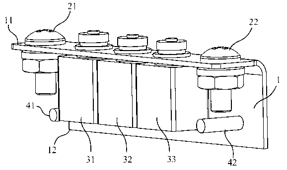
[0017] See figure 1 , Is a schematic structural diagram of an embodiment of the centralized electrical bonding module provided by the present invention.

[0018] The present invention provides a centralized electrical lap module, which includes a metal plate main body 1 and at least one wire lap point (for example, such as figure 1 The wire bonding point 21 and the wire bonding point 22 shown), at least one small bonding module (for example...


PUM


Abstract

The invention discloses a centralized electric lapping module which comprises a metal plate body, at least one guide line lapping point, at least one small size lapping module and at least one terminal lapping pile, wherein the at least one guide line lapping point, the at least one small size lapping module and the at least one terminal lapping pile are installed on the metal plate body. The guide line lapping point is used for being connected to a negative terminal of a power supply unit directly or indirectly. The small size lapping module is provided with a plurality of lapping points, and the lapping points are correspondingly connected to negative electrodes of electric equipment one to one in a contact lapping mode. The terminal lapping pile is used for being correspondingly connected to negative electrodes of the electric equipment one to one in a terminal lapping mode. The invention further discloses an electric lapping network. By means of the centralized electric lapping module and the electric lapping network, the problem that difficulty is large in designing of an electromagnetic lapping network and a negative wire reflux lapping network in a composite material airplane can be effectively solved.

Description

technical field [0001] The invention relates to the field of aircraft electrical bonding network design, in particular to a centralized electrical bonding module and an electrical bonding network. Background technique [0002] Aircraft electrical bonding mainly includes negative wire return bonding and electromagnetic bonding. Electromagnetic overlap is a very important link in aircraft design. Forming an equipotential body between the aircraft body and the equipment casing is an important means for aircraft lightning protection. It also creates a good electromagnetic environment for electronic equipment installed in the body, greatly Improve aircraft safety. [0003] Compared with metal-clad aircraft, all-composite aircraft has the characteristics of light weight and high strength. However, due to the material, the fuselage has poor conductivity, which makes it difficult for the aircraft to design lightning strikes and negative line backflow laps. Inside the fuselage, sin...

Claims


Application Information

Patent Timeline
IPC IPC(8): B64D47/00
Inventor 王杰许明轩黄平
Owner R&D INST OF CHINA AVIATION IND GENERAL AIRCRAFT
Why Eureka
Try Eureka