Lens assembly capable of realizing automatic focusing by adopting fixed focus lens

An automatic focusing and fixed focal length technology, applied in the field of optical lenses and security surveillance cameras, can solve the problems of high requirements for driving motors, large chip size, unreliability, etc., to achieve low manufacturing costs, reduced design difficulty and cost, and reliable performance. Effect

Inactive Publication Date: 2017-05-10
FOCTEK PHOTONICS LNC
View PDF6 Cites 15 Cited by
  • Summary
  • Abstract
  • Description
  • Claims
  • Application Information

AI Technical Summary

Problems solved by technology

However, in security cameras, the size of the chip is relatively large, and the chip is generally fixed on the main board. To

Method used


Image

  • Lens assembly capable of realizing automatic focusing by adopting fixed focus lens
  • Lens assembly capable of realizing automatic focusing by adopting fixed focus lens
  • Lens assembly capable of realizing automatic focusing by adopting fixed focus lens

Examples


Embodiment 1

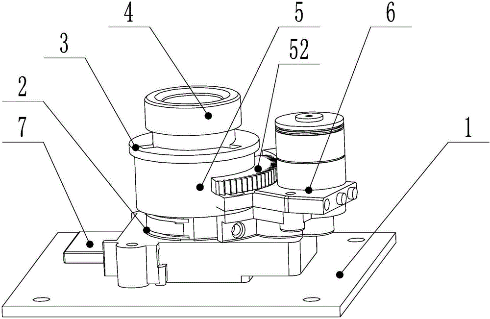
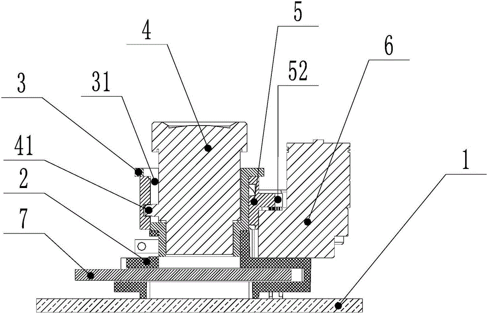
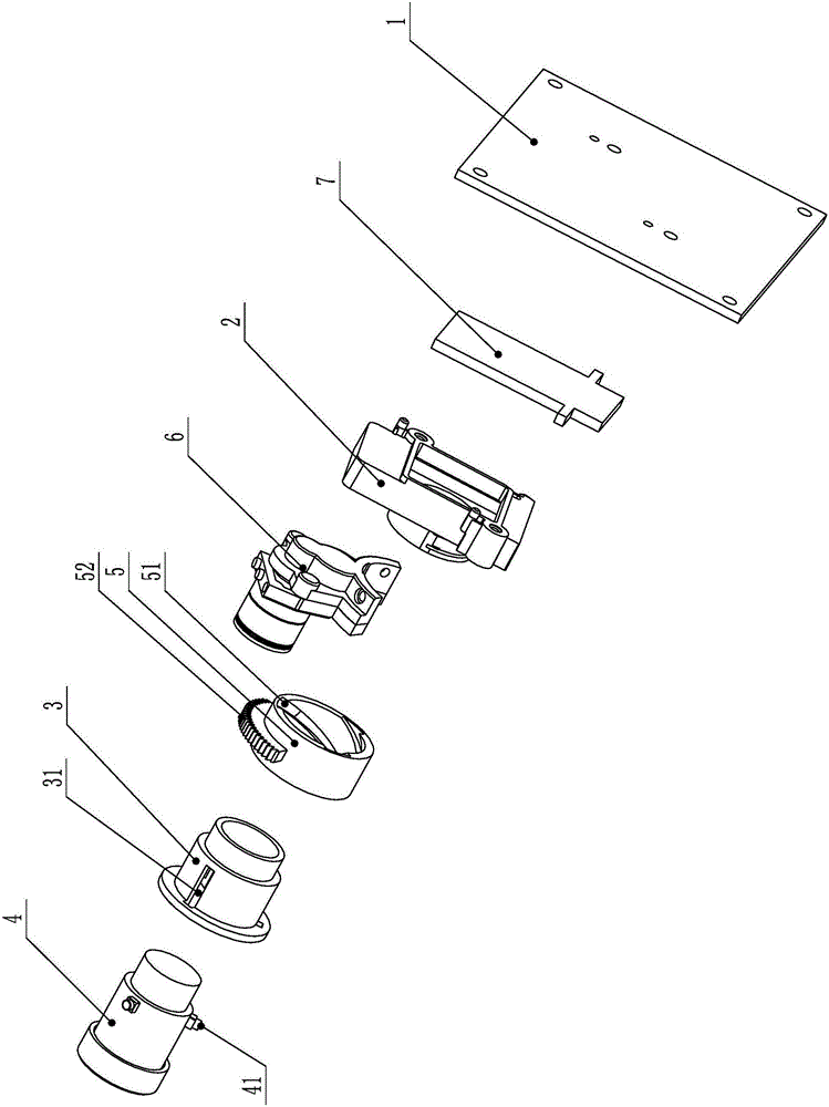
[0028] like Figure 1-3 As shown, a lens assembly that adopts a fixed focal length lens to realize automatic focusing provided by the present invention includes a motherboard chip 1 of the camera, a lens mount 2 fixed on the motherboard chip 1, and a lens mount 2 fixed on the lens mount 2. Lens fixing sleeve 3, a coaxial movable fixed-focus lens set in the lens fixing sleeve 3 and capable of moving axially relative to the lens fixing sleeve 3 4, a coaxial adjustable ring set in the outer periphery of the lens fixing sleeve 3 5 and an automatic focus control motor 6 fixed on the lens mount 2 for driving the adjusting ring 5 to rotate relative to the lens fixing sleeve 3; the outer peripheral wall of the fixed focus lens 4 is provided with guides extending radially outward Nail 41, the inner peripheral wall of the adjustment ring 5 is provided with a guide chute 51 that cooperates with the guide nail so that the fixed focus lens 4 can be axially displaced relative to the lens fi...

Embodiment 2

[0034] like Figure 4-6 As shown, the difference between Embodiment 2 and Embodiment 1 is that the guide chute is a straight slot extending parallel to the axial direction of the inner peripheral wall of the adjustment ring 5, and the through groove is along the axis of the wall of the lens fixing sleeve 3. Cam ramps that spiral forward in direction. When the adjusting ring rotates, the fixed-focus lens produces both axial displacement and rotation relative to the lens fixing sleeve.

Embodiment 3

[0036] like Figure 7-9 As shown, the difference between Embodiment 3 and Embodiment 1 is that the autofocus control motor 6 is fixed on the lens fixing sleeve 3 .


PUM


Abstract

The invention relates to a lens assembly capable of realizing automatic focusing by adopting a fixed focus lens. The lens assembly comprises a main board chip, a lens mounting seat, a lens fixing sleeve, the fixed focus lens, an adjustable ring and an automatic focusing control motor, wherein a radial outwardly-extended guiding nail is arranged on the outer peripheral wall of the fixed focus lens; a guiding sliding groove, matched with the guiding nail in a guiding manner, is formed in the inner peripheral wall of the adjustable ring; a run-through groove is formed in the sleeve wall of the lens fixing sleeve; the automatic focusing control motor is connected with the adjustable ring through a transmission apparatus; the main board chip has an automatic focusing control function; and a control line and a power line of the automatic focusing control motor are connected with an automatic focusing control interface in the main board chip. According to the lens assembly, factors of distance changes, day and night co-focusing, temperature drift and the like of a shot object are not needed to be taken into consideration in lens design, so that the design difficulty and cost of the lens are lowered; in addition, automatic focusing can be realized through the moving of the fixed focus lens in distance changes, day and night switching and high temperature and low temperature changes of the shot object, so as to obtain a clear image.

Description

technical field [0001] The invention belongs to the technical field of optical lenses and security monitoring cameras, and in particular relates to a lens assembly which adopts a fixed focal length lens to realize automatic focusing. Background technique [0002] At present, in the application field of security surveillance cameras, in order to maintain high-definition imaging in different environments (temperature, day and night), high requirements are placed on the design of the lens, that is, infrared visible (day and night) confocal, and extreme High and low temperature -40 degrees to +80 degrees without losing focus. This causes the design of the lens to be very difficult and costly. And even though day and night confocal, high and low temperature confocal are considered in the design, the result is still unsatisfactory, and there is also the problem of depth of field. At present, there are mainly two solutions. One is to use electric zoom, and to control the motor th...

Claims


Application Information

Patent Timeline
IPC IPC(8): G03B13/36G02B7/09
CPCG02B7/09G03B13/36
Inventor 黄木旺林勇杰
Owner FOCTEK PHOTONICS LNC
Why Eureka
Try Eureka