Scanning antenna

A technology for scanning antennas and conductive parts, applied in the field of scanning antennas, can solve problems such as high production costs and complex antenna bias line settings, and achieve reductions in production costs, avoid coupling loss, reduce working bandwidth, design difficulty and cost reduction Effect

Pending Publication Date: 2022-02-01
SHANGHAI TIANMA MICRO ELECTRONICS CO LTD
View PDF0 Cites 0 Cited by
  • Summary
  • Abstract
  • Description
  • Claims
  • Application Information

AI Technical Summary

Problems solved by technology

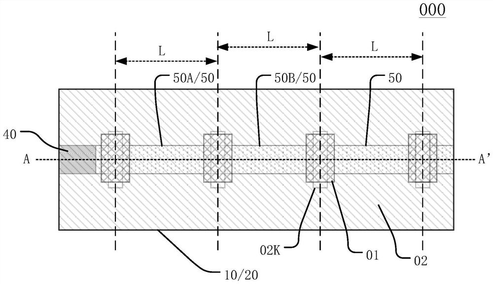
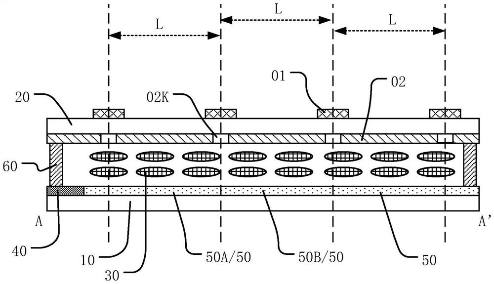
[0005] In view of this, the present invention provides a scanning antenna to realize one-dimensional beam scanning, and at the same time, it can solve t

Method used


Image

  • Scanning antenna
  • Scanning antenna
  • Scanning antenna

Examples


Embodiment Construction

[0059] Various exemplary embodiments of the present invention will now be described in detail with reference to the accompanying drawings. It should be noted that the relative arrangements of components and steps, numerical expressions and numerical values ​​set forth in these embodiments do not limit the scope of the present invention unless specifically stated otherwise.

[0060] The following description of at least one exemplary embodiment is merely illustrative in nature and in no way taken as limiting the invention, its application or uses.

[0061] Techniques, methods and devices known to those of ordinary skill in the relevant art may not be discussed in detail, but where appropriate, such techniques, methods and devices should be considered part of the description.

[0062] In all examples shown and discussed herein, any specific values ​​should be construed as exemplary only, and not as limitations. Therefore, other instances of the exemplary embodiment may have dif...


PUM


Abstract

The invention discloses a scanning antenna, and belongs to the technical field of wireless communication. The scanning antenna comprises a first substrate and a second substrate which are oppositely arranged, and a liquid crystal layer located between the first substrate and the second substrate. The scanning antenna further comprises a feed signal access end and a plurality of phase shifting units, wherein the plurality of phase shifting units are connected with each other, each phase shifting unit is connected with the feed signal access end, and the electrical lengths from at least two phase shifting units to the feed signal access end are different. One-dimensional wave beam scanning can be achieved, the scanning effect is good, bias voltage does not need to be independently applied to each phase shifting unit, arrangement of bias voltage lines can be greatly simplified, reduction of manufacturing cost and reduction of wiring difficulty are facilitated, and the scanning antenna can be applied to scenes such as high-speed rails and subway lines.

Description

technical field [0001] The present invention relates to the technical field of wireless communication, and more specifically, to a scanning antenna. Background technique [0002] Based on the anisotropic characteristics of liquid crystal molecules, the liquid crystal antenna uses electrical signals to control the arrangement of liquid crystal molecules, thereby changing the microwave dielectric parameters of each phase shifter unit, thereby controlling the phase of the microwave signal in each unit, and finally realizing the antenna radiation beam pointing. control. According to the beam scanning dimension, it can be divided into one-dimensional scanning and two-dimensional scanning antennas, which can be applied to satellite communication, 5G millimeter wave base station and other scenarios. [0003] In the existing two-dimensional scanning liquid crystal antenna, it is usually necessary to apply an independent bias voltage to each phase shifter unit to drive the deflectio...

Claims


Application Information

Patent Timeline
IPC IPC(8): H01Q3/30H01Q3/26H01Q21/00
CPCH01Q3/30H01Q3/2658H01Q21/00H01Q21/0006H01Q21/065H01Q3/44H01Q13/206H01Q3/36
Inventor 雷登明席克瑞贾振宇粟平蒋慧慧王逸李伟李欢秦锋
Owner SHANGHAI TIANMA MICRO ELECTRONICS CO LTD
Why Eureka
Try Eureka