Separable power supply circuit board, test tool and adapter plate

A technology for testing tooling and circuit boards, applied in the field of electronics, can solve problems such as complex circuit design, reduce design difficulty and cost, and improve power supply efficiency

Pending Publication Date: 2022-03-04
KUNSHAN Q TECH CO LTD
View PDF0 Cites 0 Cited by
  • Summary
  • Abstract
  • Description
  • Claims
  • Application Information

AI Technical Summary

Problems solved by technology

[0005] The present invention provides a detachable power supply circuit board and test tooling to solve or partially solve the tech

Method used


Image

  • Separable power supply circuit board, test tool and adapter plate
  • Separable power supply circuit board, test tool and adapter plate

Examples


Embodiment Construction

[0025] In order to enable those skilled in the technical field to which the application belongs to understand the application more clearly, the technical solutions of the application will be described in detail below through specific embodiments in conjunction with the accompanying drawings.

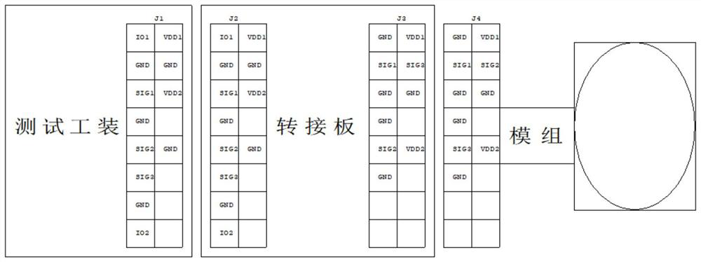
[0026] In the process of studying this embodiment, the applicant found that although the functions of electronic products such as modules are constantly being upgraded, their power consumption requirements have not changed, that is, the power circuit in the test tool is actually reusable. Therefore, in this embodiment, the power supply circuit in the test fixture is separated to form a detachable power supply circuit board. Therefore, only the design of the functional circuit needs to be considered in the test fixture, and no wiring layout for the power supply circuit is required, which can reduce the test cost. Design difficulty and cost of tooling.

[0027] Such as figure 1 As shown,...


PUM


Abstract

The invention discloses a separable power supply circuit board, a test tool and an adapter plate, a power supply circuit in the test tool is independent to form the separable power supply circuit board, so that only the design of a functional circuit needs to be considered in the test tool, wiring layout does not need to be carried out on the power supply circuit, and the test efficiency is improved. And the design difficulty and cost of the test tool can be reduced. And the power supply circuit board is provided with a power supply IC chip capable of supporting a plurality of paths of independent enabling parallel transmission, so that power can be supplied to each module at the same time, and the power supply efficiency is improved. In addition, the power supply circuit board is also integrated with a digital potentiometer IC chip to adjust a plurality of paths of independently enabled output voltages, so that the power supply requirements of different modules can be met. In addition, the power supply circuit board is further provided with an input end pluggable connector and an output end pluggable connector, so that the power supply circuit board can be independently and repeatedly used and supports plug and play.

Description

technical field [0001] The present application relates to the field of electronic technology, in particular to a detachable power supply circuit board, a test tool and an adapter board. Background technique [0002] Due to the continuous progress and development of science and technology in recent years, the future trend of electronic products will be miniaturization, integration and intelligence. The test tooling requirements for electronic products have higher and higher functions, faster update speeds, and smaller and smaller volume requirements to facilitate portability and installation. [0003] The complexity of R&D and design of test tooling hardware is getting higher and higher, and the development cycle is required to be shorter and shorter. Specifically, for the test tooling, the power circuit and the functional circuit are generally integrated on the same circuit board. The power circuit is used to supply power to electronic products, and the functional circuit ...

Claims


Application Information

Patent Timeline
IPC IPC(8): G01R1/28G01R1/04G01R31/00
CPCG01R1/28G01R1/0416G01R31/00
Inventor 刘晓凡侯栋张银凤
Owner KUNSHAN Q TECH CO LTD
Why Eureka
Try Eureka