An optical fingerprint recognition module and an electronic device

A technology of fingerprint identification module and electronic equipment, applied in the field of biometric identification, can solve the problems of fingerprint image distortion, reduction of effective field of view, etc., to achieve the effect of increasing the imaging field of view, solving the reduction of effective field of view, and improving imaging quality

Inactive Publication Date: 2019-05-21
SHENZHEN GOODIX TECH CO LTD
View PDF4 Cites 14 Cited by
  • Summary
  • Abstract
  • Description
  • Claims
  • Application Information

AI Technical Summary

Problems solved by technology

[0005] This application provides an optical fingerprint identification module and electronic equipment, which increases the imaging field of view, improves the quality of fingerprint imaging, improves the accuracy of fingerprint identification, and solves the problem of the effective visual field of the optical fingerprint identification module under the existing LCD screen. Field reduction and distortion of the generated fingerprint image

Method used


Image

  • An optical fingerprint recognition module and an electronic device
  • An optical fingerprint recognition module and an electronic device
  • An optical fingerprint recognition module and an electronic device

Examples


Embodiment 1

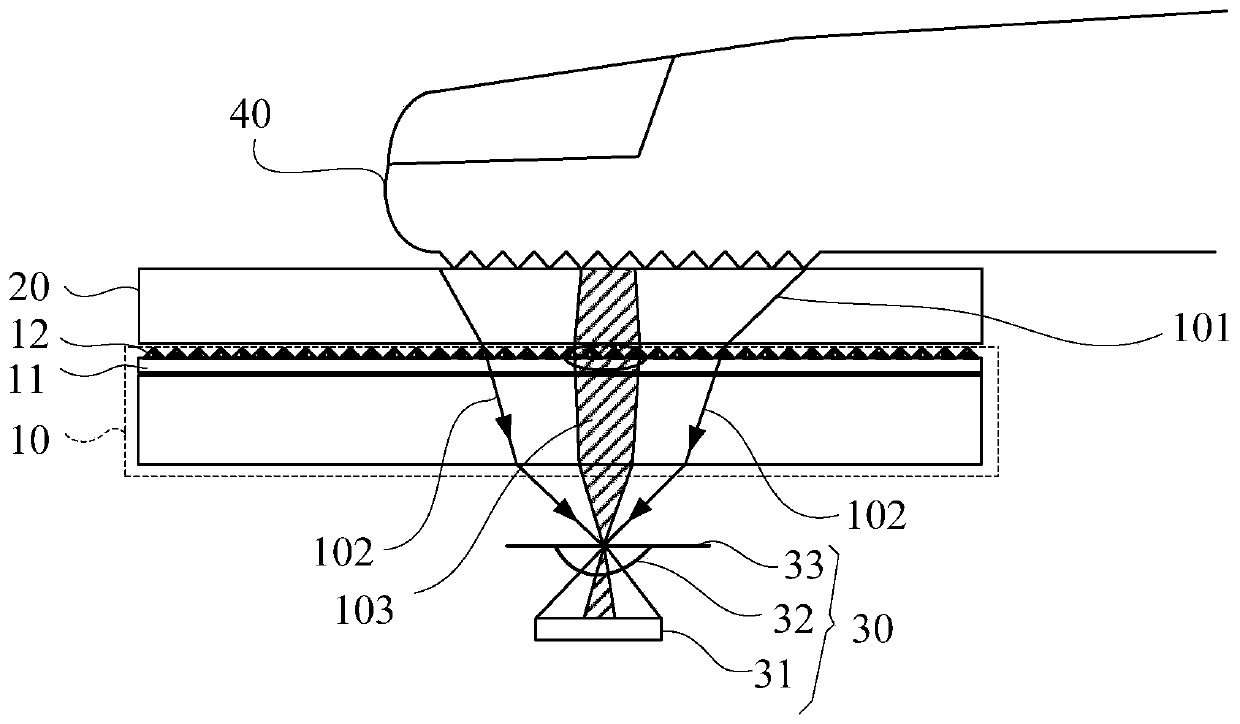
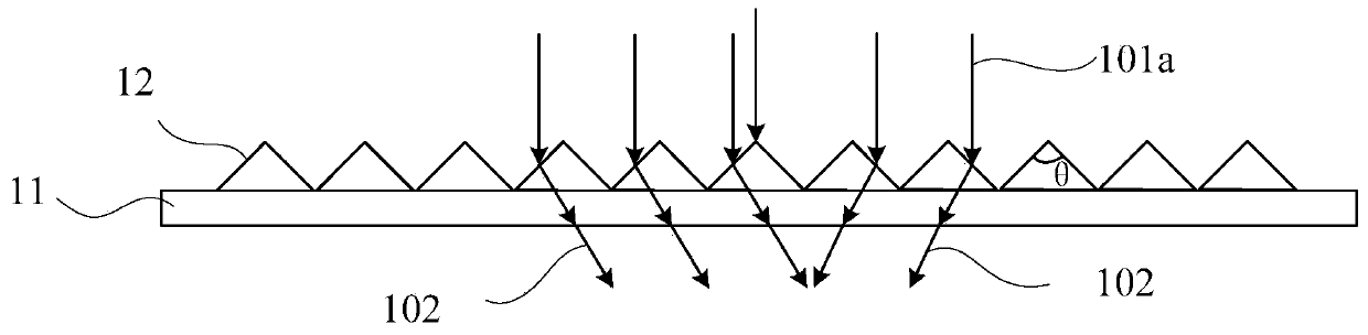
[0055] Figure 2A A schematic diagram of the optical fingerprint recognition module provided under the LCD display screen provided by Embodiment 1 of the present application, Figure 2B for Figure 2A Schematic diagram of the top view structure of optical elements and prism junctions of the optical fingerprint recognition module in China, Figure 2C A schematic diagram of the refraction of light between the optical element and the prism structure in the optical fingerprint recognition module provided in Embodiment 1 of the present application, Figure 2D Another schematic diagram of the structure of the optical fingerprint identification module provided in Embodiment 1 of the present application when it is set under the LCD display screen, Figure 2E for Figure 2D Schematic diagram between the optical elements and the prism structure of the optical fingerprint recognition module in the middle.

[0056] see Figures 2A-2C As shown, the optical fingerprint identification m...

Embodiment 2

[0071] image 3 It is a schematic diagram of the optical fingerprint recognition module provided under the LCD display screen provided in the second embodiment of the present application.

[0072] The difference between this embodiment and the foregoing embodiments is: in this embodiment, see image 3 As shown, the optical hole 3011 on the optical element 301 is a vertical hole, that is, when the optical hole 3011 is opened on the optical element 301, the optical hole 3011 is a straight hole perpendicular to the horizontal direction, but in order to ensure that the optical hole 3011 has a specific angle The refracted light ray 102 is selected. In this embodiment, the optical element 301 is arranged obliquely, so that the vertical optical hole 3011 on the optical element 301 is inclined at a specific angle with the optical element 301. At this time, the inclined optical hole 3011 and the vertical The included angle β between the straight directions matches the prism included a...

Embodiment 3

[0077] Figure 4 A schematic diagram of the optical fingerprint recognition module provided under the third embodiment of the present application when it is set under the LCD display screen.

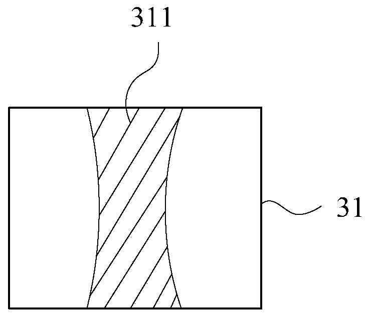
[0078] The difference between this embodiment and the foregoing embodiments is: in this embodiment, see Figure 4 As shown, the optical hole 3011 on the optical element 301 is a vertical hole, that is, the optical hole 3011 is a straight hole in the optical element 301, and the optical element 301 is horizontally arranged on the optical sensor element 302, in order to realize the refraction at a specific angle The light 102 is selected. In this embodiment, the inner wall of the optical hole 3011 is set to be able to perform total reflection on the refracted light 102 at a preset angle. That is, in this embodiment, the inner wall of the optical hole 3011 has The characteristic of total reflection, so that the incident light can be selected in a targeted manner, and only the light that me...


PUM


Abstract

An optical fingerprint recognition module and an electronic device are provided. The optical fingerprint recognition module includes: an optical sensing element (302) and an optical element (301). Theoptical element (301) has a plurality of optical holes (3011) parallel to each other such that refracted light obtained after light reflected by a ginger is refracted by a prism structure of a backlight module (10) can pass through the optical holes (3011) and enter a sensing area of the optical sensing element (302). Through the optical fingerprint recognition module and the electronic device, the imaging field is enlarged, quality of fingerprint imaging is improved, and fingerprint recognition accuracy is higher.

Description

technical field [0001] The application relates to biometric identification technology, in particular to an optical fingerprint identification module and electronic equipment under an LCD screen. Background technique [0002] With the development of biometric technology, more and more terminals are equipped with biometric modules (such as optical fingerprint recognition modules, iris recognition modules or face recognition modules), among which, the specific work of biometric modules The principle is: the sensor in the biometric module receives the light reflected by the living body and forms a skin characteristic image, compares the skin characteristic image with the stored image, and completes functions such as fingerprint recognition and living body detection. When applied in a terminal, it is usually arranged under an organic light-emitting diode (Organic Light-Emitting Diode, OLED for short) display screen or an LCD display screen. [0003] At present, when the optical ...

Claims


Application Information

Patent Timeline
Patent Type & Authority Applications(China)
IPC IPC(8): G06K9/00
CPCG06F18/00
Inventor 谢浩
Owner SHENZHEN GOODIX TECH CO LTD
Why Eureka
Try Eureka