Centrifuge and swing-out rotor

A centrifuge and rotor technology, applied in centrifuges and other directions, can solve problems such as large space and large centrifuge size, and achieve the effect of reducing energy demand, ensuring stability, and reducing inertial mass

Pending Publication Date: 2019-05-24
埃佩多夫欧洲股份公司
View PDF9 Cites 2 Cited by
  • Summary
  • Abstract
  • Description
  • Claims
  • Application Information

AI Technical Summary

Problems solved by technology

[0014] The disadvantage of such oscillating rotors is that they occupy a relatively large space due to the oscillating movement of the suspension that occurs during the outswing, so that the dimensions of the centrifuge for centrifugation must be relatively large compared to fixed-angle rotors

Method used


Image

  • Centrifuge and swing-out rotor
  • Centrifuge and swing-out rotor
  • Centrifuge and swing-out rotor

Examples


Embodiment Construction

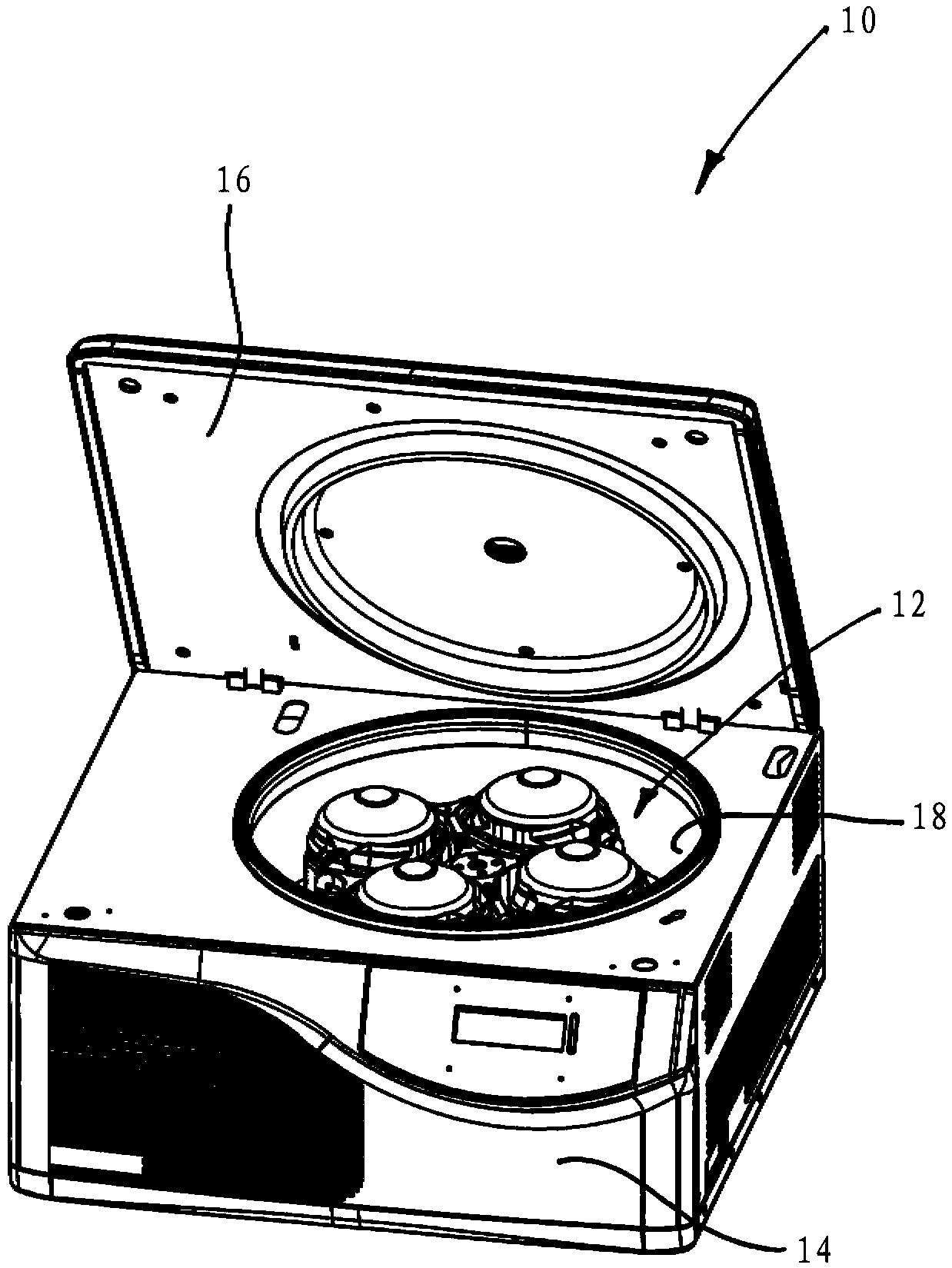
[0036] Figure 1 to Figure 5 A first example of a centrifuge 10 is shown with an oscillating rotor 12 inserted therein.

[0037] The centrifuge 10 is configured as a laboratory centrifuge having a housing 14 with a cover 16 . In the centrifuge container 18 of the centrifuge 10 , the oscillating rotor 12 is arranged on a drive shaft (not shown) of a centrifuge motor (not shown).

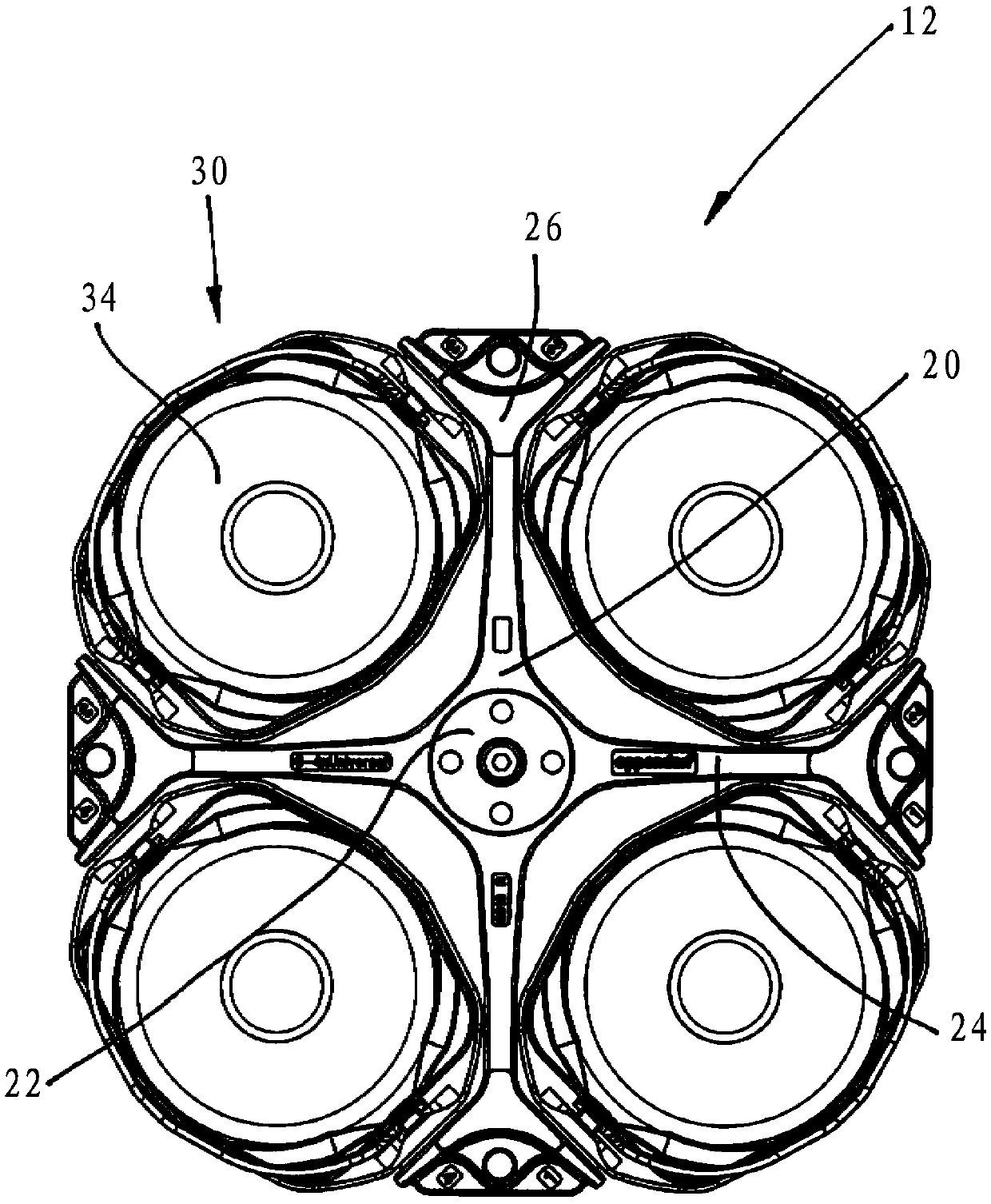
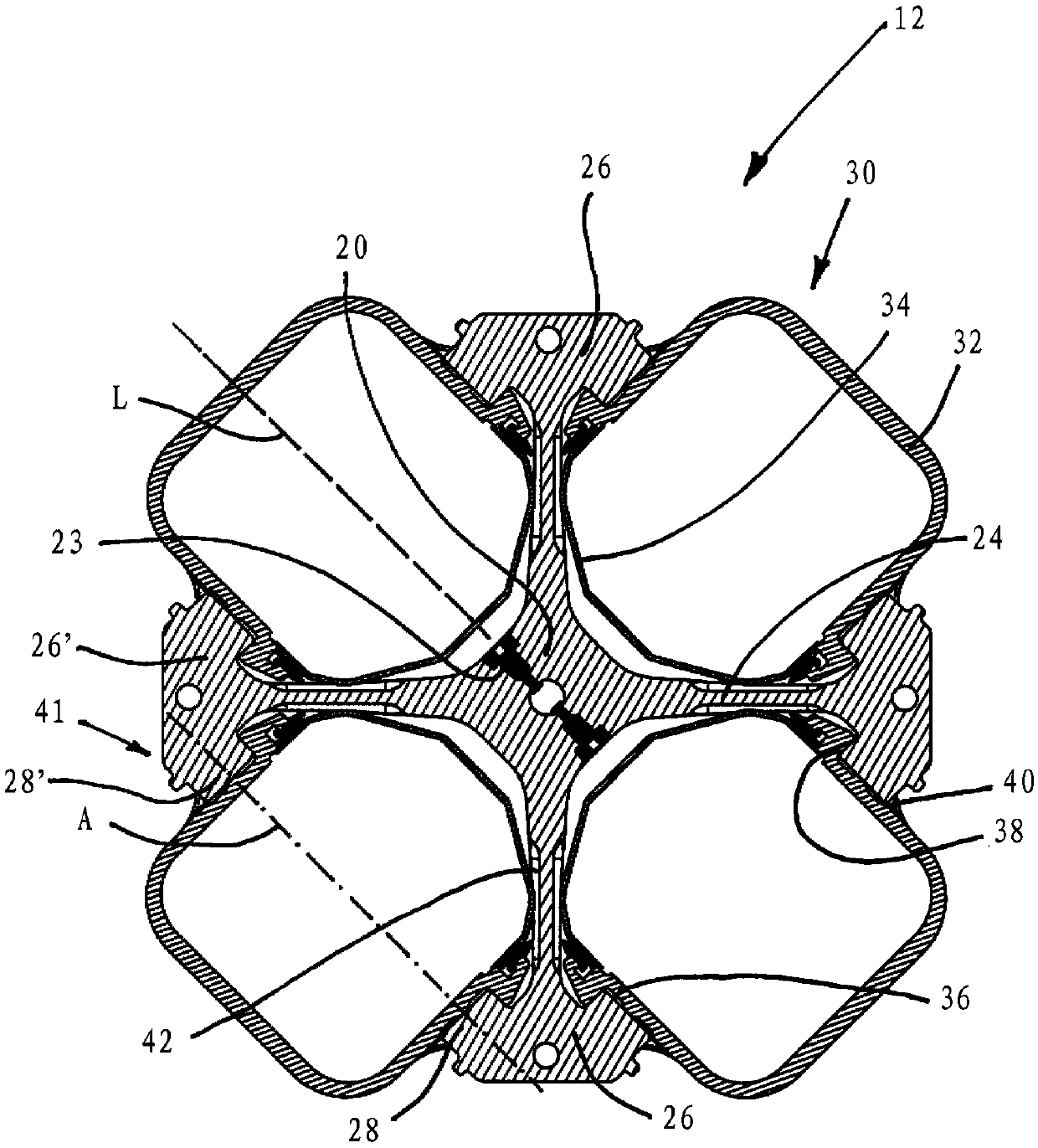
[0038] The oscillating rotor 12 has a rotor base body 20 with a hub 22 which is coupled to the drive shaft via screws 23 . The rotor base body 20 has four rotor arms 24 which are each arranged on a hub 22 which are offset from each other by 90° in the circumferential direction. The rotor arms 24 open out into arm branches 26 in which two retaining pins 28 are arranged. The oppositely arranged retaining pins 28 , 28 ′ of the two oppositely arranged arm branches 26 , 26 ′ are aligned such that they are aligned and thus form the swing-out axis A .

[0039]The suspension 30 is configured as a tub 32 a...


PUM


Abstract

A centrifuge includes a swing rotor. Rotor arms of the swing rotor have recesses into which hangers of the swing rotor at least partially swing in a swung-out state. As a result, the centrifuge container and thus also the centrifuges are more compact, because the swinging-out requires less space. An inertial mass of the swing rotor is reduced due to the recesses provided therein, whereby energy consumption, primarily when starting the centrifuge, is significantly reduced.

Description

technical field [0001] The present disclosure relates to swinging bucket centrifuges and rotors for swinging bucket centrifuges. Background technique [0002] Centrifuge rotors are used in centrifuges, especially laboratory centrifuges, to separate components of a sample centrifuged therein based on sample density. Use higher spin speeds to achieve high separation rates. A laboratory centrifuge is a centrifuge in which the rotor preferably runs at a speed of at least 3000 revolutions per minute, preferably at least 10000 revolutions per minute, in particular at least 15000 revolutions per minute and is usually placed on a bench. In order to place them on the bench, they may have a form factor of less than 1m x 1m x 1m; thus they have limited space. Preferably, the depth of the device is limited to a maximum of 70 cm. [0003] Such centrifuges are used in fields such as medicine, pharmacy, biology and chemistry. [0004] In most cases, centrifugation of the sample at a ce...

Claims


Application Information

Patent Timeline
Patent Type & Authority Applications(China)
IPC IPC(8): B04B5/04B04B7/00
CPCB04B5/0421B04B2011/046
Inventor S·库纳特H·G·科恩
Owner 埃佩多夫欧洲股份公司
Why Eureka
Try Eureka