Turnover box based on corner lock fastening

A turnover box and corner lock technology, which is applied in the direction of locking equipment, rigid containers, containers, etc., can solve the problems of pollution, turnover box fasteners scratching each other, loss of transported goods in the box, etc., and achieve the effect of avoiding damage

Pending Publication Date: 2019-05-24
郭泽和
View PDF0 Cites 1 Cited by
  • Summary
  • Abstract
  • Description
  • Claims
  • Application Information

AI Technical Summary

Problems solved by technology

[0006] The purpose of the present invention is to solve the problem that two adjacent turnover box fasteners often scratch each other in a limited space, resulting in damage to the L-shaped lock hook, lock buckle and box board, and the problem that during transportation The L-shaped hook and buckle are not completely locked during transportation, resulting in loss or pollution of the transported goods in the box

Method used


Image

  • Turnover box based on corner lock fastening
  • Turnover box based on corner lock fastening
  • Turnover box based on corner lock fastening

Examples


Embodiment 1

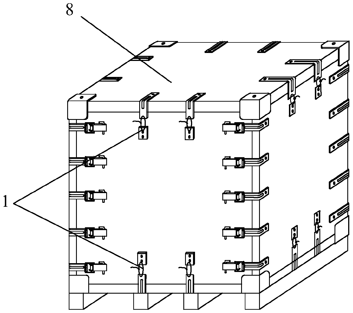
[0023] Such as figure 1 As shown, a turnover box (for transporting liquid) based on corner lock fastening includes a hollow box body 8 composed of six box panels, and the box cover of the hollow box body 8 and the adjacent side panels pass through The corner lock 1 is fastened and connected; the side box panels can be connected by a lock, or can be connected by the corner lock 1 (choose according to the demand). The top corner of the hollow box 8 is provided with an anti-collision corner .

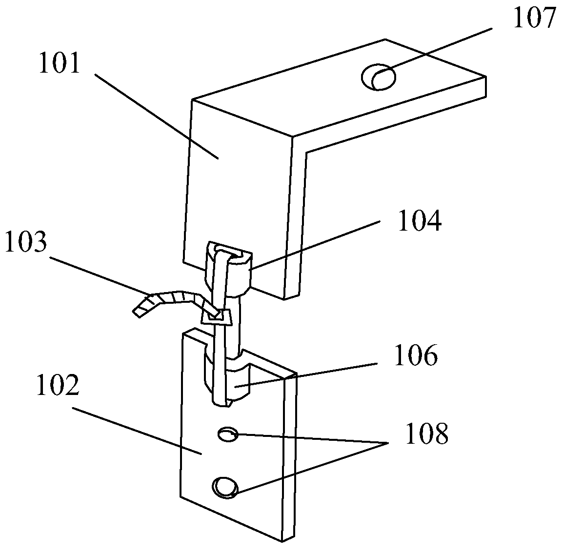
[0024] The corner lock 1 includes an elongated L-shaped locking piece 101 arranged at the corner of the hollow box 8, a straight locking piece 102 on the box plate adjacent to the corner where the L-shaped locking piece 101 is located, And the locking bar 103 connecting the L-shaped locking piece 101 and the straight locking piece 102 . The locking bar 103 is locked by a one-time tensioning locking bar to prevent losses caused by misoperation or illegal operation during transportation. ...

Embodiment 2

[0026] Embodiment 2: as figure 1 As shown, a turnover box (for transporting solids) based on corner lock fastening includes a hollow box body 8 composed of six box panels, and the adjacent box panels of the hollow box body 8 pass through corner locks 1 Tight connection; the side box panels can be connected by locks, or can be connected by the corner lock 1 (selected according to requirements), and the top corner of the hollow box body 8 is provided with an anti-collision fixed angle.

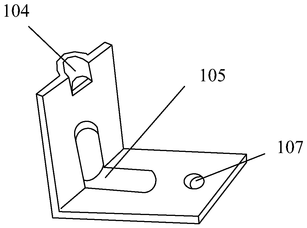
[0027] Such as image 3 As shown, the corner lock 1 includes an L-shaped locking piece 101 arranged at the corner of the hollow box 8, a straight locking piece 102 on the box plate adjacent to the corner where the L-shaped locking piece 101 is located, And the locking bar 103 connecting the L-shaped locking piece 101 and the straight locking piece 102 . The locking bar 103 is locked by a one-time tensioning locking bar to prevent losses caused by misoperation or illegal operation during transp...


PUM


Abstract

The invention discloses a turnover box based on corner lock fastening. The turnover box comprises a hollow box body (8) composed of six box plates, and the adjacent box plates of the hollow box body (8) are in fastening connection by corner locks (1). The corner locks (1) include L-shaped locking pieces (101) disposed at corners of the hollow box body (8), straight locking pieces (102) on the boxplates adjacent to the corner positions in which the L-shaped locking pieces (101) are located and locking bars (103) connecting the L-shaped locking pieces (101) with the straight locking pieces (102). The turnover box can effectively avoid that in a limited space such as a container or a car box, fasteners on both sides of two adjacent turnover boxes often rub each other, and damage to the box plates and the fasteners is further avoided. During the transportation, a box cover and a box bottom of a box can be completely locked, and the condition that pollution or loss of liquid or solid cargos transported inside the box is caused due to the fact that the box cover is opened manually or non-manually is avoided.

Description

technical field [0001] The invention relates to a new type of turnover box for transportation, more specifically, to a turnover box based on corner lock fastening. Background technique [0002] The non-demolition and zero turnover box in the prior art is a box body composed of six box panels. After the six box panels of the box body are connected by connectors at the edge junctions, a hollow box is formed. For accommodating and transporting liquid or solid packages, the connecting parts are all connected by L-shaped hooks and locks. In the prior art, when the L-shaped lock hook and the lock buckle are connected together, the width of the box body in the front, rear, left and right directions will be increased. [0003] When this kind of turnover box is used for side-by-side packing or unloading of containers or automobiles, due to the limited space, the two adjacent turnover boxes need to be very close. The thickness of the above-mentioned L-shaped lock hook itself is more ...

Claims


Application Information

Patent Timeline
IPC IPC(8): B65D6/24B65D55/02
Inventor 郭泽和
Owner 郭泽和
Why Eureka
Try Eureka