Wall/ column and foundation connection structure and construction method thereof

A technology for connecting structures and foundations, applied in infrastructure engineering, building construction, construction, etc., can solve the problems of high standardization, poor seismic effect, etc., and achieve the effect of reducing usage, fast construction, and reducing construction personnel.

Pending Publication Date: 2019-05-24
GUOZHU HABITAT ENG CONSULTANTS
2 Cites 0 Cited by

AI-Extracted Technical Summary

Problems solved by technology

There are many defects in the direct splicing of the prefabricated foundation and the wall/column in the prior art. For example, it is necessary to build modules to bind steel bars during the constr...

Method used

According to an embodiment of the present invention, wall/column provided by the invention and foundation connection structure are used for prestressed tension construction building, and foundation comprises base, local wall/column and foundation beam, and local wall/column both sides are downward The depression forms a depression, and the two ends of the foundation beam are sunken inward, so that the two ends of the foundation beam form a boss, the boss vertically opens a first hole through the boss, and the partial wall/column vertic...

Abstract

The invention provides a wall/column and foundation connection structure and a construction method thereof. A foundation comprises a base, a local wall/column and a foundation beam, two sides of the local wall/column sink downwards to form sunken portions, two ends of the foundation beam sink inwards to enable bosses to be formed at two ends of the foundation beam, a first hole penetrating throughthe bosses is vertically formed in the bosses, and a second hole is vertically formed in the local wall/column. When the foundation beam is built on the local wall/column, the first hole is aligned with the second hole; when the wall/column is built on the foundation beam, a third hole is aligned with the first hole, and pre-tightening force is exerted on the wall/column, the foundation beam andthe local wall/column through pre-tightening ribs. The wall/column and foundation connection structure and the construction method thereof have the advantages that modular construction can be realized, both the standardization degree and the construction speed are high, the whole construction process can be completely realized through a dry method, and template consumption and construction personnel are both reduced.

Application Domain

Technology Topic

Image

  • Wall/ column and foundation connection structure and construction method thereof
  • Wall/ column and foundation connection structure and construction method thereof
  • Wall/ column and foundation connection structure and construction method thereof

Examples

  • Experimental program(1)

Example Embodiment

[0027] By referring to exemplary embodiments, the objects and functions of the present invention and the methods for achieving these objects and functions will be clarified. However, the present invention is not limited to the exemplary embodiments disclosed below; it can be implemented in different forms. The essence of the description is only to help those skilled in the relevant art to comprehensively understand the specific details of the present invention.
[0028] In the following, embodiments of the present invention will be described with reference to the accompanying drawings, and related technical terms should be well known to those skilled in the art. In the drawings, the same reference signs represent the same or similar components, or the same or similar steps, unless otherwise specified.
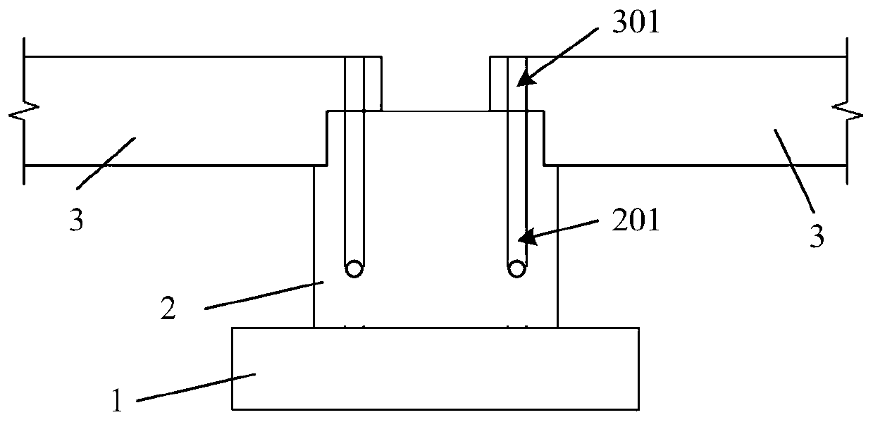
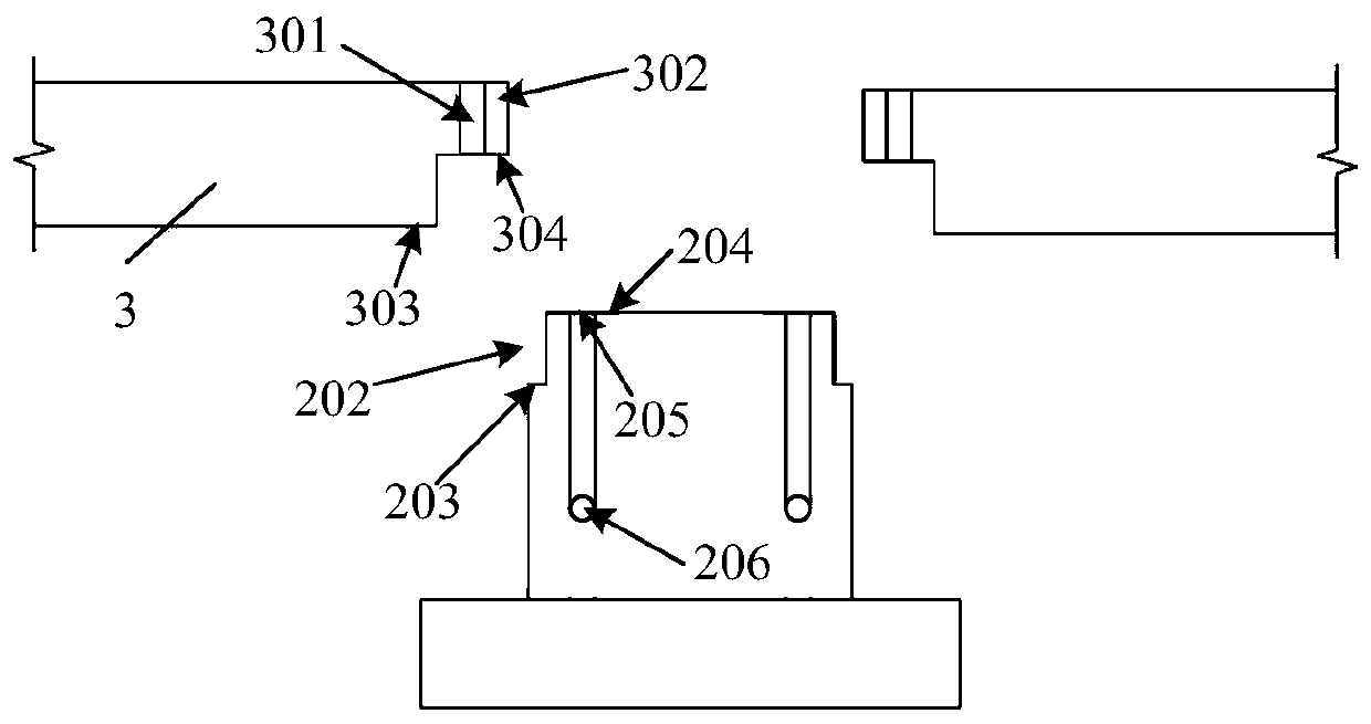
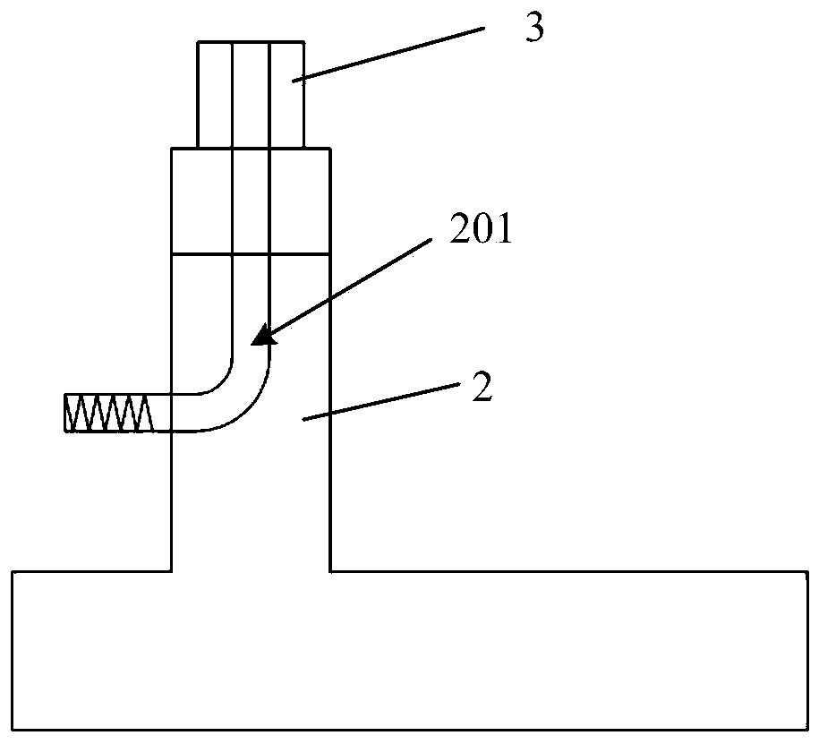
[0029] According to an embodiment of the present invention, the wall/column and foundation connection structure provided by the present invention is used for prestressed construction construction. The foundation includes a base, a partial wall/column, and a foundation beam. The two sides of the partial wall/column are recessed downward to form a depression Part, the two ends of the foundation beam are recessed inward, so that the two ends of the foundation beam form bosses. The bosses are vertically opened with first holes penetrating the bosses, and local walls/pillars are vertically opened with second holes. The hole goes through the side of the partial wall/column, and the wall/column is provided with a third hole that penetrates longitudinally. When the wall/column is built on the foundation beam, the third hole is aligned with the first hole. The invention adopts the specific above-mentioned basic structure to be connected to the wall/column, so that the construction of templates can be omitted during the construction process, and the standardization requirements of prefabricated parts can be reduced.
[0030] The technical solutions of the present invention are explained in detail in the following embodiments, such as figure 1 A schematic diagram showing the foundation of the wall/column and foundation connection structure of the present invention, figure 2 The exploded schematic diagram of the partial wall/column and foundation beam of the present invention is shown. According to an embodiment of the present invention, a wall/column and foundation connection structure for a prestressed construction building. The foundation includes a base 1, a partial wall/column 2 and a foundation beam 3. According to the present invention, the base 1, the partial wall/column 2 and the foundation beam 3 in this embodiment are prefabricated in the factory, and the base 1 and the partial wall/column 2 are integrally formed.
[0031] The two sides of the partial wall/column 2 are recessed downward to form a recess 202. The two ends of the foundation beam 3 are recessed inward, so that the two ends of the foundation beam form a boss 302. The boss 302 is vertically provided with a first through the boss 302. In the hole 301, the partial wall/column 2 is vertically provided with a second hole 201, and the second hole 201 penetrates along the side of the partial wall/column. Specifically, such as image 3 A side view showing the foundation of the wall/column and foundation connection structure of the present invention, combined figure 2 with image 3 , The second hole 201 of the partial wall/column 2 penetrates from the vertical opening 205 at the top of the partial wall column, extends to the inside of the partial wall/column 2, and passes through the lateral opening 206 on the side of the partial wall/column 2. In some embodiments, a construction hole may be opened on the side of the partial wall/column 2, and the second hole 201 penetrates into the construction hole.
[0032] When the foundation beam 3 is built on the partial wall/column 2, the upper side 203 of the recess 202 supports the bottom surface 303 of the foundation beam 3; the upper surface 204 of the partial wall/column 2 supports the bottom surface 304 of the boss 302, and the first hole 301 It is aligned with the second hole 201, specifically, the first hole 301 is aligned with the vertical opening 205 of the second hole. The pre-tightening force is applied to the foundation beam 3 and the partial wall/column 2 through the pre-tensioning ribs passing through the first hole 301 and the second hole 302. According to the embodiment of the present invention, the first hole 301 and/or the second hole 301 is embedded with casing. In some preferred embodiments, the embedded casing is a corrugated metal casing, and the pre-tensioning rib is pre-stressed steel or Stranded wire.
[0033] Such as Figure 4 The top view of the basic structure of the present invention is shown. In this embodiment, the prefabricated foundation used for prestressed tension construction is an "L" structure. In some embodiments, the present invention provides The prefabricated foundation can be "一" type or "T" type structure.
[0034] Such as Figure 5 Shown is a schematic diagram of the connection between the wall/column of the present invention and the foundation. The wall/column 4 of the present invention is prefabricated in the factory. The wall/column 4 is provided with a third longitudinally through hole 401. When the wall/column 4 is built on the foundation beam 3, the third The hole 401 is aligned with the first hole 301, and the pre-tensioning force is applied to the wall/column 4, the foundation beam 3 and the partial wall/column 2 through the pre-tensioning ribs passing through the third hole, the first hole and the second hole. According to the present invention, a casing is embedded in the third hole 401 and/or the first hole 301 and/or the second hole 201. The embedded casing is corrugated metal casing, and the pre-tensioning rib is pre-stressed steel bar or steel strand.
[0035] In some embodiments, the connection between the wall/column 4 and the foundation beam 3 is spliced ​​by stepped fitting, such as Image 6 A schematic diagram of the connection between the wall/column and the foundation beam in an embodiment of the present invention is shown. The upper side of the foundation beam 3 is provided with a protrusion 305, and the lower side of the wall/column 4 is located at the position of the third cavity 401 with a groove 402. A hole 301 penetrates the protruding portion 305. When the wall/column 4 is built on the foundation beam 3, the protruding portion 305 is embedded in the groove 402, and the third hole 401 is aligned with the first hole 301. In other embodiments, the bottom of the wall/column is recessed from the wall surface to form a tongue and groove, and the boss 302 of the foundation beam 3 is embedded in the tongue and groove.
[0036] According to an embodiment of the present invention, a construction method for a wall/column and foundation connection structure of a prestressed construction building includes:
[0037] (1) Prefabricated walls/columns, bases, partial walls/columns and foundation beams.
[0038] The wall/column, the base, the partial wall/column and the foundation beam of the present invention are all prefabricated in the workshop. The wall/column is provided with a third longitudinally through hole, and the two sides of the partial wall/column are recessed downward to form a depression. The two ends are recessed inward, so that the two ends of the foundation beam form a boss. The boss is vertically opened with a first hole through the boss, and the local wall/column is vertically opened with a second hole. The second hole is along the part of the wall/column. Through the side.
[0039] (2) Build foundation beams and walls/columns.
[0040] The prefabricated wall/column bases, partial walls/columns and foundation beams in the workshop are transported to the construction site, the partial walls/columns are fixed, and the foundation beams are erected on the partial walls/columns. The upper side of the recesses supports the bottom surface of the foundation beams. The upper surface of the wall/column supports the bottom surface of the boss, and the first hole is aligned with the second hole; the wall/column is built on the foundation beam so that the third hole and the first hole Aligned.
[0041] (3) Pre-tensioning is applied to walls/columns, foundation beams and local walls/columns.
[0042] Pre-tightening ribs are pierced in the third hole, the first hole and the second hole, the pre-tightening rib is stretched and the slurry is poured into the third hole, the first hole and the second hole.
[0043] The wall/column and foundation connection structure and its construction method provided by the invention can reduce the standardization requirements of prefabricated parts, reduce the use of templates, and increase the seismic performance of the wall/column structure.
[0044] In combination with the description and practice of the present invention disclosed herein, other embodiments of the present invention are easily thought of and understood by those skilled in the art. The description and embodiments are only considered to be exemplary, and the true scope and spirit of the present invention are defined by the claims.

PUM

no PUM

Description & Claims & Application Information

We can also present the details of the Description, Claims and Application information to help users get a comprehensive understanding of the technical details of the patent, such as background art, summary of invention, brief description of drawings, description of embodiments, and other original content. On the other hand, users can also determine the specific scope of protection of the technology through the list of claims; as well as understand the changes in the life cycle of the technology with the presentation of the patent timeline. Login to view more.

Similar technology patents

Classification and recommendation of technical efficacy words

  • Fast construction
  • High degree of standardization

Method of making wall block

InactiveUS20050016106A1Fast constructionMaximize useMould separation apparatusLighting and heating apparatusEngineeringBuilding construction
Owner:KEYSTONE RETAINING WALL SYST
Why Eureka
Try Eureka