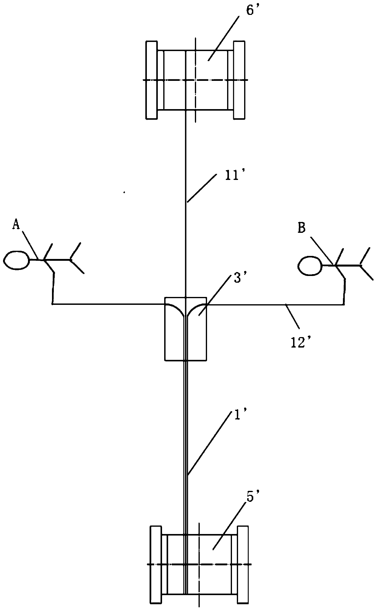
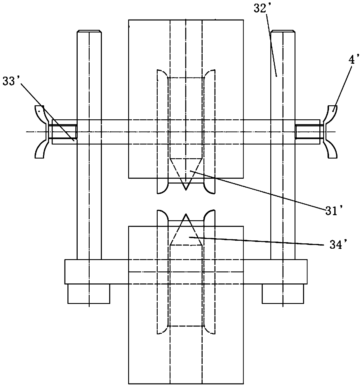
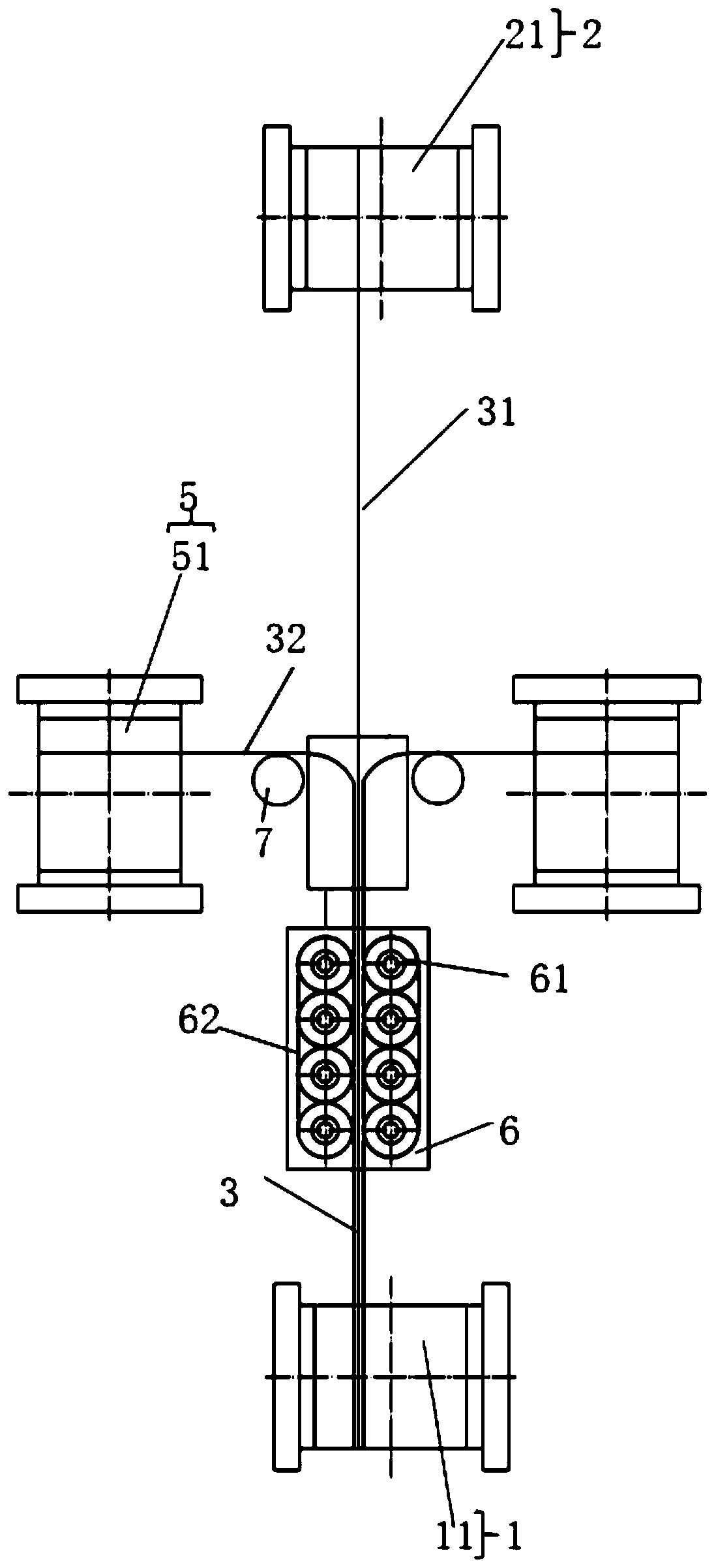
Cable stripping unit and cable stripping device with scale labels

A technology of ruler scale and optical cable, applied in the direction of fiber mechanical structure, etc., can solve the problems of difficult to control the depth, unfavorable separation of the steel belt sheath and skin, puncturing of the cable core 11, etc., and achieve the effect of accurately controlling the cutting depth.

Inactive Publication Date: 2019-05-24
GUANGDONG HENGTONG PHOTOELECTRIC SCI & TECH +1
View PDF5 Cites 0 Cited by
  • Summary
  • Abstract
  • Description
  • Claims
  • Application Information

AI Technical Summary

Problems solved by technology

When the cross bar is not horizontal, the position of the cable between the upper knife 31' and the lower knife 34' may change when the upper knife 31' and the lower knife 34' are cutting, resulting in the cutting depth of the stripped optical cable 1' Either deep or shallow, the depth is difficult to control
If the stripping is too deep, the yarn of the cable core 11' will be broken or the casing will be punctured. If the stripping is too shallow, it will not be conducive to the separation of the steel belt sheath 12' from the cable core 11'

Method used


Image

  • Cable stripping unit and cable stripping device with scale labels
  • Cable stripping unit and cable stripping device with scale labels
  • Cable stripping unit and cable stripping device with scale labels

Examples


Embodiment Construction

[0053] The technical solutions of the present invention will be further described below in conjunction with the accompanying drawings and through specific implementation methods.

[0054] In order to make the purpose, technical solutions and advantages of the embodiments of the present invention clearer, the technical solutions in the embodiments of the present invention will be clearly and completely described below in conjunction with the drawings in the embodiments of the present invention. Obviously, the described embodiments It is a part of embodiments of the present invention, but not all embodiments. The components of the embodiments of the invention generally described and illustrated in the figures herein may be arranged and designed in a variety of different configurations.

[0055] Accordingly, the following detailed description of the embodiments of the invention provided in the accompanying drawings is not intended to limit the scope of the claimed invention, but ...


PUM


Abstract

The invention relates to the technical field of optical cables, and discloses a cable stripping unit and a cable stripping device with scale labels. The cable stripping unit comprises a lower cutter assembly, supporting rods, an adjusting piece and an upper cutter assembly, wherein the supporting rods are arranged in the vertical direction and are separately arranged on the two sides of the lowercutter assembly; scales are arranged on the supporting rods on the two sides; the adjusting piece is arranged horizontally, is connected with the two supporting rods, and can slide vertically along the supporting rods; the upper cutter assembly is connected with the adjusting piece; the adjusting piece can drive the upper cutter assembly to lift; the upper cutter assembly and the lower cutter assembly are opposite to each other; and an optical cable is arranged between the upper cutter assembly and the lower cutter assembly. The distance between an upper cutter and a lower cutter can be adjusted accurately so as to control the cutting depth of a cable.

Description

technical field [0001] The invention relates to the technical field of optical cables, in particular to a cable stripping unit and a scale-stripping cable stripping device. Background technique [0002] For optical cable manufacturers, under the premise that their optical performance, environmental and mechanical properties meet the customer's established requirements and industry standards, in order to achieve intensive and full utilization of resources, usually the optical cable or the outer sheath of the stock that has been seriously stripped during the process Scratch and strip the cable. Secondary use of the cable core. Generally, the cable core and the steel belt sheath are effectively separated by longitudinal stripping with a "sharp cone" knife. [0003] Existing cable stripping devices such as figure 1 and figure 2 As shown, the device includes an unwinding assembly 5' and a retracting assembly 6', the unwinding assembly 5' is used to place the cable 1' to be s...

Claims


Application Information

Patent Timeline
Patent Type & Authority Applications(China)
IPC IPC(8): G02B6/44
Inventor 曾辉李小军胡珍王倩倩金永良林丽华詹翠怡
Owner GUANGDONG HENGTONG PHOTOELECTRIC SCI & TECH
Why Eureka
Try Eureka