
Ammonia injection optimization adjustment device and method based on inlet flow field distribution of denitration device

A technology for adjusting devices and inlet flow, which is applied in the field of flue gas denitrification, can solve the problems of excessive ammonia injection and uneven distribution of flue gas flow, and achieve the solution of excessive and insufficient ammonia injection, uneven distribution of inlet flow field, and data processing process. concise effect

Pending Publication Date: 2019-05-28
NORTH CHINA ELECTRICAL POWER RES INST +1
View PDF8 Cites 4 Cited by
  • Summary
  • Abstract
  • Description
  • Claims
  • Application Information

AI Technical Summary

Problems solved by technology

During the actual adjustment process, it was found that there was an uneven distribution of flue gas velocity on the ammonia injection section perpendicular to the flue gas flow direction in the inlet flue of the denitrification device
The traditional ammonia injection system does not consider the uneven distribution of the flow field here. Therefore, the traditional device will not adjust the ammonia injection ratio according to the actual flow field conditions, resulting in insufficient ammonia injection in places with a large flue gas flow rate, and the flue gas flow rate is low. Excessive spraying of ammonia in small places

Method used


Image

  • Ammonia injection optimization adjustment device and method based on inlet flow field distribution of denitration device
  • Ammonia injection optimization adjustment device and method based on inlet flow field distribution of denitration device
  • Ammonia injection optimization adjustment device and method based on inlet flow field distribution of denitration device

Examples


Embodiment 1

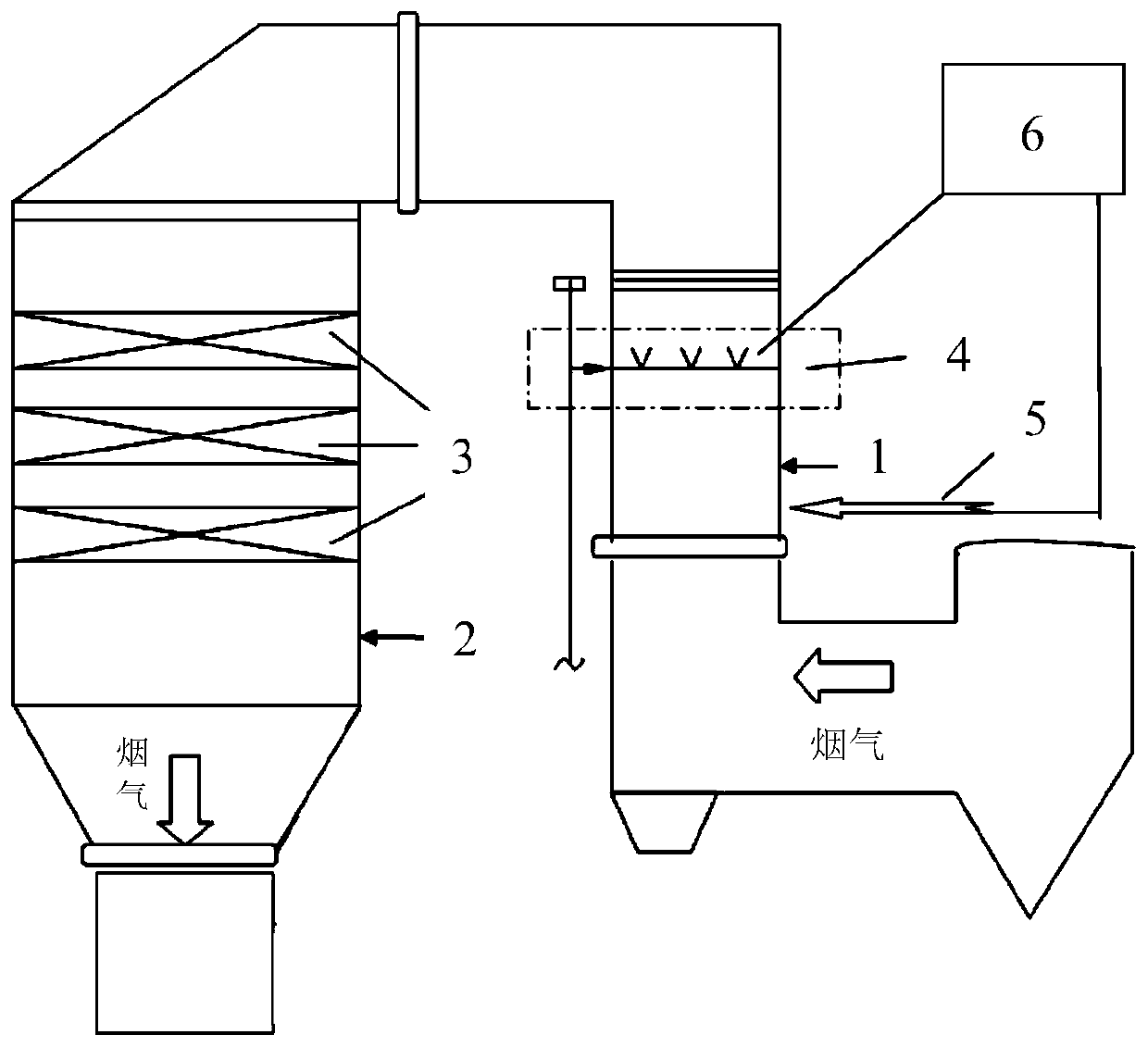
[0069] This embodiment provides an ammonia injection optimization adjustment device based on the distribution of the inlet flow field of the denitrification device (SCR denitrification device, including the catalyst module 3 and the ammonia injection grid 4), wherein the structural diagram of the device is as follows figure 1 shown, from figure 1 As can be seen from the figure, it includes several speed measuring tubes 5 and control units 6;

[0070] Wherein, the velocity measuring tube is a velocity measuring tube for measuring the dynamic pressure of the flue gas at the injection point on the ammonia injection plane in the flue at the inlet 1 of the denitrification device;

[0071] Each injection point is also provided with a corresponding ammonia injection regulating valve;

[0072] The control unit is electrically connected to several velocity measuring tubes respectively, and it includes a first computing unit and a second computing unit; the first computing unit is used...

Embodiment 2

[0076] This embodiment provides a method for optimizing the adjustment of ammonia injection based on the distribution of the inlet flow field of the denitrification device (SCR denitrification device), wherein the method is to use the optimal adjustment of ammonia injection based on the distribution of the inlet flow field of the denitrification device provided in Example 1 device, which includes the following steps:

[0077] (1) Determine the number of test injection points (ammonia injection points) on the ammonia injection plane in the flue at the entrance of the SCR denitrification device, which specifically includes:

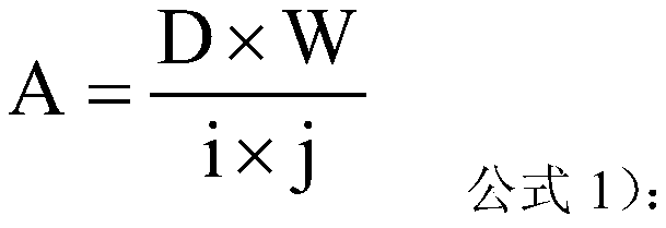
[0078] The depth D of the ammonia injection plane at the inlet of the SCR denitration device in a coal-fired power plant is 3m, and the width W is 5m. Query the engineering design drawings of the denitrification device of the power plant, and determine the layout of the ammonia injection points on the ammonia injection plane as (3×5). Arrange (3×5) measuri...


PUM


Abstract

The invention provides an ammonia injection optimization adjustment device and method based on inlet flow field distribution of a denitration device. The ammonia injection optimization adjustment method comprises the following steps that (1) gridding is carried out on ammonia injection planes in an inlet flue of the denitration device to determine the number of injection points on the ammonia injection planes; (2) the smoke dynamic pressure at the injection points is measured separately by using a speed measuring tube, and a maximum value of the smoke dynamic pressure at the injection points is determined; and (3) the opening degree of an ammonia injection regulating valve is obtained by calculating according to the smoke dynamic pressure at each injection point and the maximum value of the smoke dynamic pressure at the injection points. The ammonia injection optimization adjustment method based on the inlet flow field distribution of the denitration device converts the initial smoke dynamic pressure into the opening degree of an ammonia injection distribution valve through the operation of a control unit, the data processing process is simple and clear, the problem of uneven distribution of the inlet flow field of the denitration device is solved, the problem of overlarge and insufficient ammonia injection can be solved from the upstream, and the actual operation of the denitration device of the power plant can be guided to a certain extent.

Description

technical field [0001] The invention relates to an ammonia injection optimization adjustment device and method based on the flow field distribution at the inlet of a denitrification device, and belongs to the technical field of flue gas denitrification. Background technique [0002] In order to comply with the national ultra-low emission requirements of coal-fired units and the trend of flexible peak-shaving of coal-fired power plants, power plants have higher and higher performance requirements for thermal power unit denitrification devices. After the coal-fired unit has been in operation for a long time, the ammonia escape at the outlet of the denitrification device will be unevenly distributed on the same cross-section. During the actual adjustment process, it was found that the flue gas flow velocity distribution was uneven on the ammonia injection section perpendicular to the flue gas flow direction in the inlet flue of the denitrification device. The traditional ammon...

Claims


Application Information

Patent Timeline
Patent Type & Authority Applications(China)
IPC IPC(8): B01D53/86G05D7/06B01D53/56
Inventor 刘高军郭玥杜磊姜龙李庆赵振宁曹红加张清峰
Owner NORTH CHINA ELECTRICAL POWER RES INST
Learn More