Eureka AIR delivers breakthrough ideas for toughest innovation challenges, trusted by R&D personnel around the world.

An optical microscopic imaging method and device for on-line monitoring under high temperature conditions

A high-temperature state, optical microscopy technology, applied in the direction of measuring devices, optics, microscopes, etc., can solve the problems of complex systems, close distances between microscopes and heat sources, and achieve large imaging working distances, adjustable test environments, and wide measurement temperature ranges Effect

Active Publication Date: 2021-12-24
NORTHWEST INST OF NUCLEAR TECH
View PDF8 Cites 0 Cited by
  • Summary
  • Abstract
  • Description
  • Claims
  • Application Information

AI Technical Summary

Problems solved by technology

[0005] In order to solve the problems of the existing high-resolution dynamic optical microscopic imaging scheme, such as complex system and short distance between the microscope and the heat source, the present invention proposes a new optical microscopic imaging method and device for on-line monitoring under high temperature conditions

Method used


Image

  • An optical microscopic imaging method and device for on-line monitoring under high temperature conditions
  • An optical microscopic imaging method and device for on-line monitoring under high temperature conditions

Examples


Embodiment 1

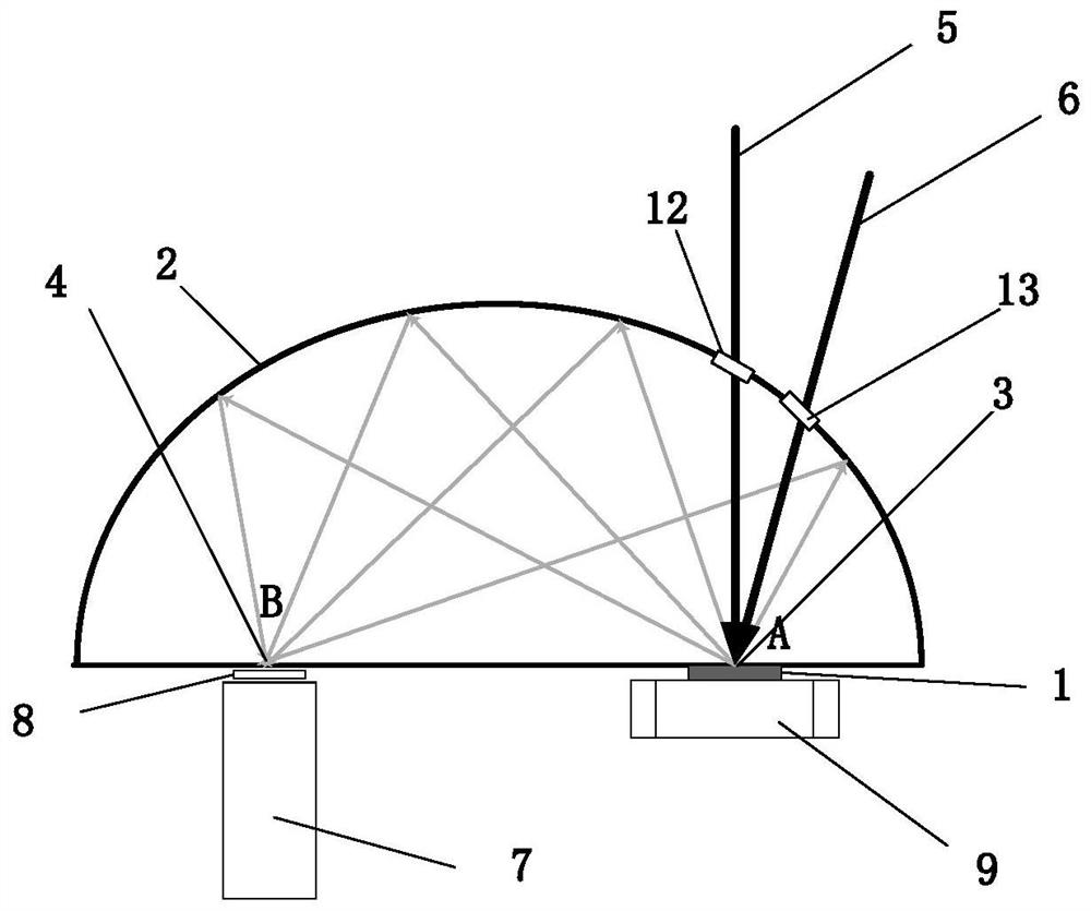
[0031] see figure 1 , the sample 1 is placed at the focal point A of the conjugate imaging plane 2, and the optical microscope 7 is placed at the focal point B; the sample is installed on the position adjustment mechanism 9, which can adjust the position of the sample in the three-dimensional direction to ensure The area center is always on focus A. The sample 1 is heated by the laser 6 to achieve a high temperature state; the laser light source is located outside the conjugate imaging plane, and the heating laser 6 enters through the light window 13 to heat the sample 1 . The illumination light 5 irradiates the surface of the sample 1 through the light window 12, and an image is formed at the focal point B. A filter 8 is installed in front of the optical microscope to filter out the laser signal to eliminate the interference to the imaging. Use an optical microscope to magnify the conjugated image to obtain a microscopic image.

Embodiment 2

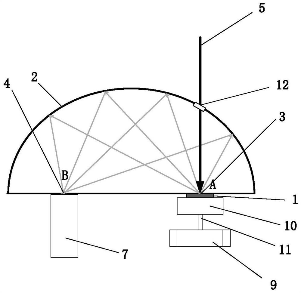
[0033] see figure 1 , the sample 1 is placed at the focal point A of the conjugate imaging plane 2, and the optical microscope 7 is placed at the focal point B; the sample is installed on the position adjustment mechanism 9, which can adjust the position of the sample in the three-dimensional direction to ensure The area center is always on focus A. A heater 10 is arranged on the back of the sample to achieve a high temperature state; a heat insulation component 11 is arranged between the heater 10 and the position adjustment mechanism 9 . The illumination light 5 irradiates the surface of the sample 1 through the light window 12, and an image is formed at the focal point B. Use an optical microscope to magnify the conjugated image to obtain a microscopic image.


PUM


Abstract

The present invention proposes an optical microscopic imaging method and device for on-line monitoring under high temperature conditions, aiming to solve the problems of existing high-resolution dynamic optical microscopic imaging schemes such as complex systems and short distances between microscopes and heat sources. The method comprises the following steps: 1) placing the sample and the optical microscope at focus A and focus B of the conjugate imaging plane respectively; 2) heating the sample and maintaining a high temperature state; 3) irradiating the sample with illumination light Surface, produce diffuse reflection, and then reflected by the conjugate imaging surface, the conjugate image is received and enlarged by the optical microscope to obtain a microscopic image; 4) If it is necessary to observe different areas of the sample surface, move the sample to ensure that the The center of the measurement area is always on the focal point A, and the microscopic image is obtained according to step 3).

Description

technical field [0001] The invention belongs to the field of optical microscopic analysis, and relates to an on-line optical microscopic imaging method and device. Background technique [0002] Microscope, as one of the greatest inventions in human history, has a very wide range of applications in life medicine, biological science, materials science and many other fields. Using microscopes and microscopic imaging techniques, cells, tissue structure and morphology, microscopic topography of materials / devices can be easily observed, and changes in cells can be monitored in real time. Microscopes are mainly divided into two categories: optical microscopes and electron microscopes. Electron microscopes have the unparalleled high resolution of optical microscopes, but they have high requirements on the working environment and are difficult to achieve non-destructive observation. Relatively speaking, optical microscopes are relatively inexpensive and simple to operate, but the d...

Claims


Application Information

Patent Timeline
Patent Type & Authority Patents(China)
IPC IPC(8): G02B21/36G02B21/30G02B21/00G01N21/84
Inventor 吴丽雄冯国斌张检民陈绍武
Owner NORTHWEST INST OF NUCLEAR TECH
Why Eureka
Eureka Blog
Learn More