Light guides

a technology of light guide and guide rod, which is applied in the direction of lighting and heating apparatus, lighting heating/cooling arrangements, instruments, etc., can solve the problems of compromising light uniformity, increasing the complexity of the production process of these devices, and components susceptible to mechanical damage, etc., to reduce/no dark spots, reduce power requirements, and lighten the structure

Active Publication Date: 2011-12-29
DESIGN LED PRODS
View PDF19 Cites 50 Cited by
  • Summary
  • Abstract
  • Description
  • Claims
  • Application Information

AI Technical Summary

Benefits of technology

[0034]The present invention seeks to provide one or more of the following advantages: a more uniform light guide device (including uniform or substantially uniform luminance) with reduced/no dark spots when viewed in use; efficient light distribution resulting in lower power requirements; a thinner, lighter structure; a device comprising a reduced number of system components. The devices according to the present invention may advantageously be used for 2-d and 3-d dimming. In particular, the present invention seeks to provide effective thermal management of backlight devices without adversely affecting the optical performance.
[003

Problems solved by technology

The integration of fluorescent lamps or LEDs to the edge of the transparent light guide is not a straightforward process and thus significantly increases the complexity of the production process for these devices.
In addition, edge coupling of the light sources renders these components susceptible to mechanical damage during both the production process and the normal use of the device.
This has the benefit of creating a thin and efficient backlight but has the disadvantage of compromising the light uniformity.
Existing solutions to this problem tend to add considerable thickness to the backlight.
If the heat dissipates into a liquid crystal panel for example, the display quality may be adversely affected.
Because the t

Method used


Image

  • Light guides
  • Light guides
  • Light guides

Examples


example 1

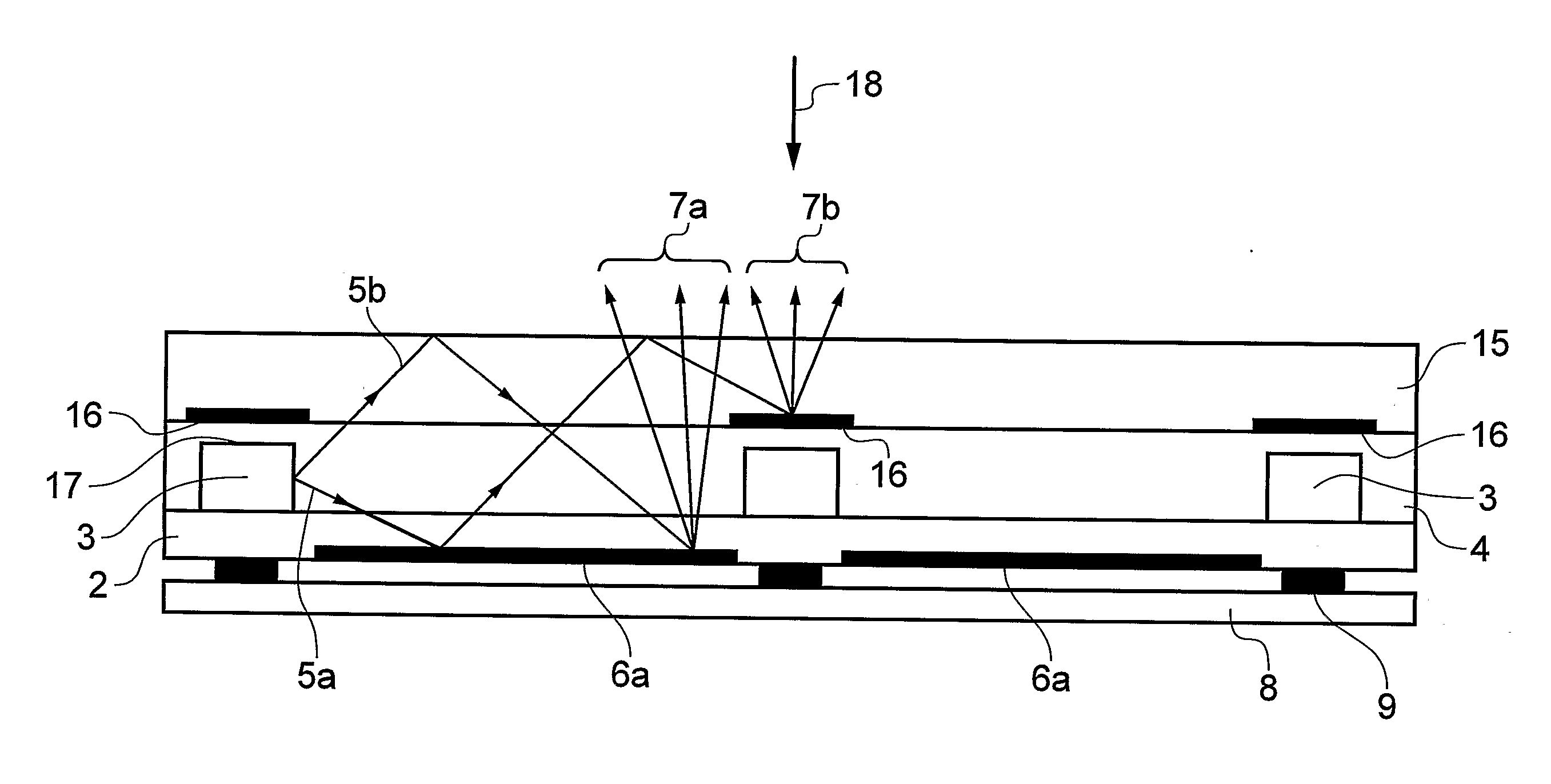
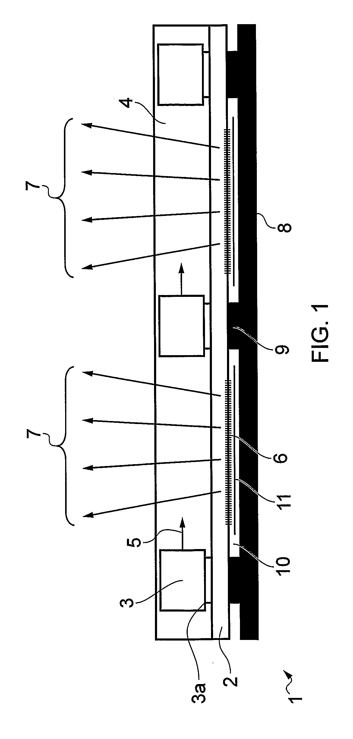
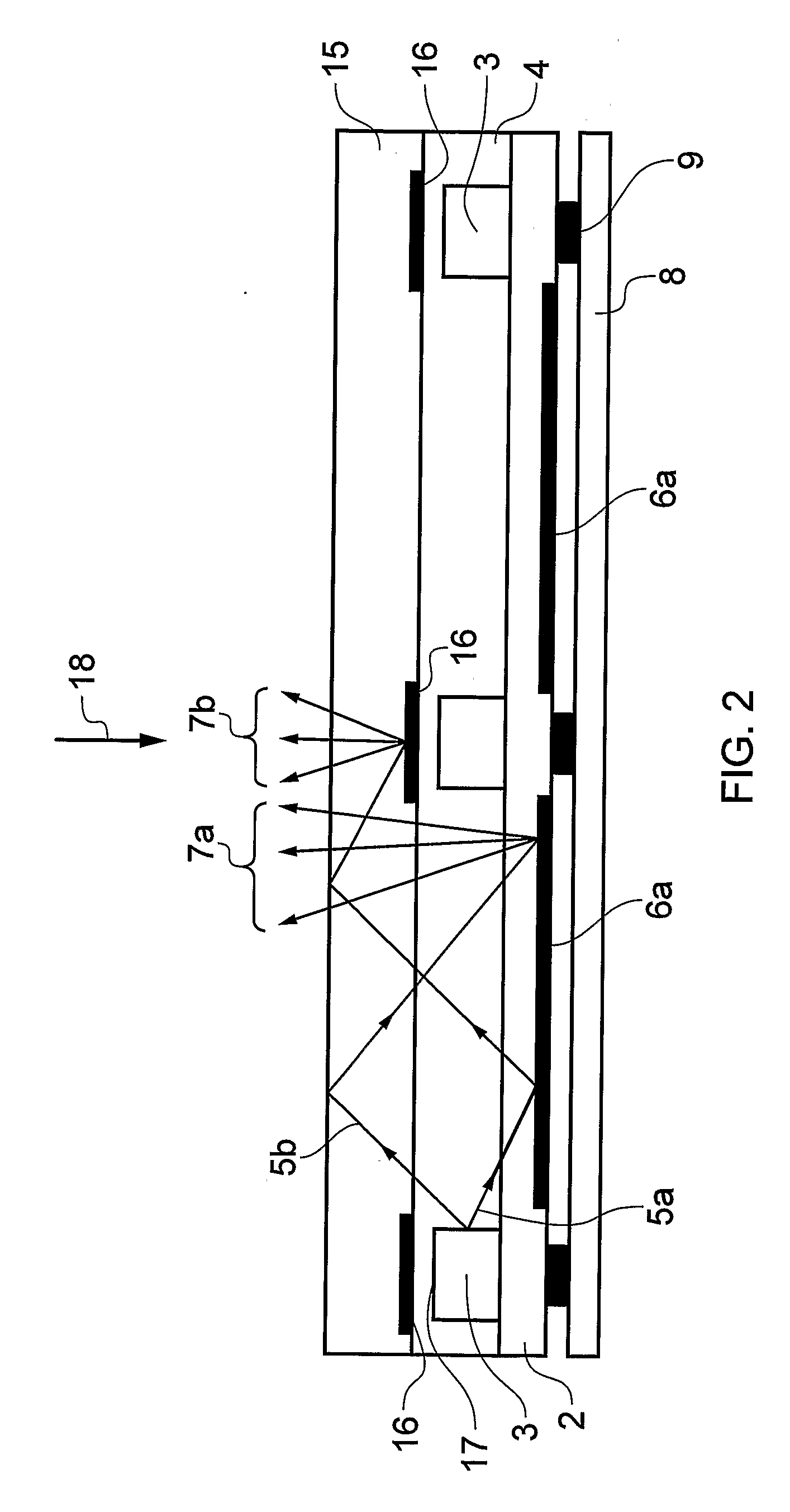
[0089]A device in accordance with the invention was constructed as follows. A 0.125 mm thick sheet of transparent polyester was used as a base substrate. A scattering structure comprising white lines of ink was printed onto the underside of the polyester film. The ink used was a white acrylic based, UV curing polymer screen printable ink which is commercially available. On the opposite (or top) side of the polyester film was printed conducting tracks (silver particle loaded conducting epoxy) and conducting adhesive in order to mount a number of LEDs (Stanley Tw1145ls-tr) onto the substrate and provide suitable electrical connections onto the conducting ink tracks. A cavity, about 0.7 mm deep was formed around the perimeter of the base substrate using a cavity layer structure. The cavity was then filled with UV curing transparent polymer (Dymax 4-20688), thus forming a first light guide layer. A spacing element was positioned and secured on the first light guide layer and the diffuse...


PUM

PropertyMeasurementUnit
Thicknessaaaaaaaaaa
Angleaaaaaaaaaa
Flexibilityaaaaaaaaaa

Abstract

This invention relates to light guide devices and methods of manufacture. The light guide device is suitable for use in a range of applications, particularly in connection with the backlighting of displays, for example, liquid crystal displays.

Description

FIELD OF THE INVENTION[0001]This invention relates to light guide devices and methods of manufacture. The light guide devices are suitable for use in a range of applications, particularly in connection with the backlighting of displays, for example, liquid crystal displays.BACKGROUND OF THE INVENTION[0002]A number of light guiding devices are known. These devices are employed for a range of functions including illumination, backlighting, signage and display purposes. Typically, the devices are constructed from an injection moulded or machined transparent plastic component, where a light source, such as a fluorescent lamp or a plurality of light emitting diodes (LEDs), is integrated by means of mechanical attachment at the edge of the transparent plastic component.[0003]Common to all of these devices is the fact that light from the light source is guided through a transparent guide, typically made of plastic, by total internal reflection. For backlighting applications, light is emitt...

Claims


Application Information

Patent Timeline
IPC IPC(8): F21V7/00F21V29/00B23P11/00F21V5/00
CPCG02B6/0043G02B6/0068Y10T29/49826G02B6/0085G02B6/0073
Inventor GOURLAY, JAMES
Owner DESIGN LED PRODS
Why Eureka
Try Eureka