Optical Particle Sensor with Exhaust-Cooled Optical Source

a technology of optical source and optical particle sensor, which is applied in the field of optical particle sensing, can solve the problems of increasing process reliability, reducing process downtime, and generating a substantial amount of heat from optical sources that illuminate samples with high radiant power, so as to improve the operating life and performance of these components, reduce operating temperature, and reduce the effect of thermal managemen

Active Publication Date: 2008-10-09
PARTICLE MEASURING SYST
View PDF64 Cites 7 Cited by
  • Summary
  • Abstract
  • Description
  • Claims
  • Application Information

AI Technical Summary

Benefits of technology

[0009]The present invention provides systems and methods for cooling one or more heat-producing elements within an optical particle sensor or sensing system. Methods and systems of the present invention use exhausted sample fluid conducted through regions of the optical particle sensor to provide effective thermal management, such as cooling, of selected device components. In some embodiments, for example, exhaust from an optical particle sensor is brought into thermal contact with a heat-producing element, such as an optical source. Transfer of thermal energy to the exhaust flow is used in the present invention to cool selected heat generating device components so as to reduce their operating temperature, thereby enhancing operating lifetime and performance of these components. The exhausted sample fluid in thermal contact with the heat producing element(s) is subsequently removed from the optical particle sensor so as to dissipate heat and provide thermal management of the sensing system.
[0010]Cooling strategies of the present invention utilize a temperature differential between the sample fluid introduced into a particle sensor and one or more heat-producing elements of the sensing system to provide targeted device component cooling. In particular, cooling of the heat-producing element is optionally passive, thereby minimizing or avoiding a need for active power-consuming cooling devices, such as thermoelectric cooling devices. Systems and methods of the present invention are particularly well suited for applications wherein low power consumption is advantageous, such as optical particle sensors that are part of a factory-integrated monitoring system, including sensors powered by a DC battery of low voltage and current.
[0011]Disclosed herein are basic particle sensor configurations combined with fluidic structures for cooling optical sources in sensor systems. In an embodiment, a flowing sample fluid is introduced into a sample chamber for optical analysis. After the sample has been optically analyzed in the sample chamber, sample fluid is removed and circulated along one or more specific fluidic pathways selected to establish thermal contact with a heat producing optical source element. In an aspect, substantially all the sample fluid is used to cool a heat-generating device. In another aspect, only a portion of the sample fluid is used to cool a heat-generating device, such as a portion of the sample fluid that is not required for cooling being exhausted to the environment. Alternatively, a first portion of sample fluid is directed to cool a first heat-generating device and a second portion of sample fluid is directed to cool a second heat-generating device. Alternatively, a plurality of heat-generating devices are cooled in series by a single flow-path of sample fluid such as essentially all the sample fluid or a portion of the sample fluid, as desired, depending on operating conditions and temperatures. Fluidic structures useful for establishing thermal contact include, but are not limited to, plenum chambers, air flow cavities, and optionally heat sink structures, or any combination thereof. Heat transfer provided by circulating exhausted sample fluid that is of a lower temperature than the temperature of the optical source provides cooling of the optical source without the need for any additional power or complex device configurations. Accordingly, the invention provides an elegant, versatile and reliable mechanism for maximizing optical source lifetime in a particle sensor by reducing operating temperatures.

Problems solved by technology

Optical sources that illuminate samples with high radiant power also, however, generate a substantial amount of heat.
Longer optical source lifetime increases process reliability and decreases process downtime.
Cooling mechanisms commonly used for optical sources in particle counters include active thermoelectric cooling which often require a substantial amount of power.
Accordingly, standard cooling techniques such as enclosure fans are inappropriate for these applications.
The available solutions, however, suffer from one or more limitations of complexity, expense, undesirable additional energy requirements, or are incompatible with the particle sensors of the present invention.
Although particle sensors may have some residual cooling attributed to the fact that relatively cool sample fluid flows through the sample chamber that interacts with the optical source, they suffer from the limitation of not being able to adequately cool the optical source.

Method used


Image

  • Optical Particle Sensor with Exhaust-Cooled Optical Source
  • Optical Particle Sensor with Exhaust-Cooled Optical Source
  • Optical Particle Sensor with Exhaust-Cooled Optical Source

Examples


example 1

Plenum-Cooled Particle Sensor

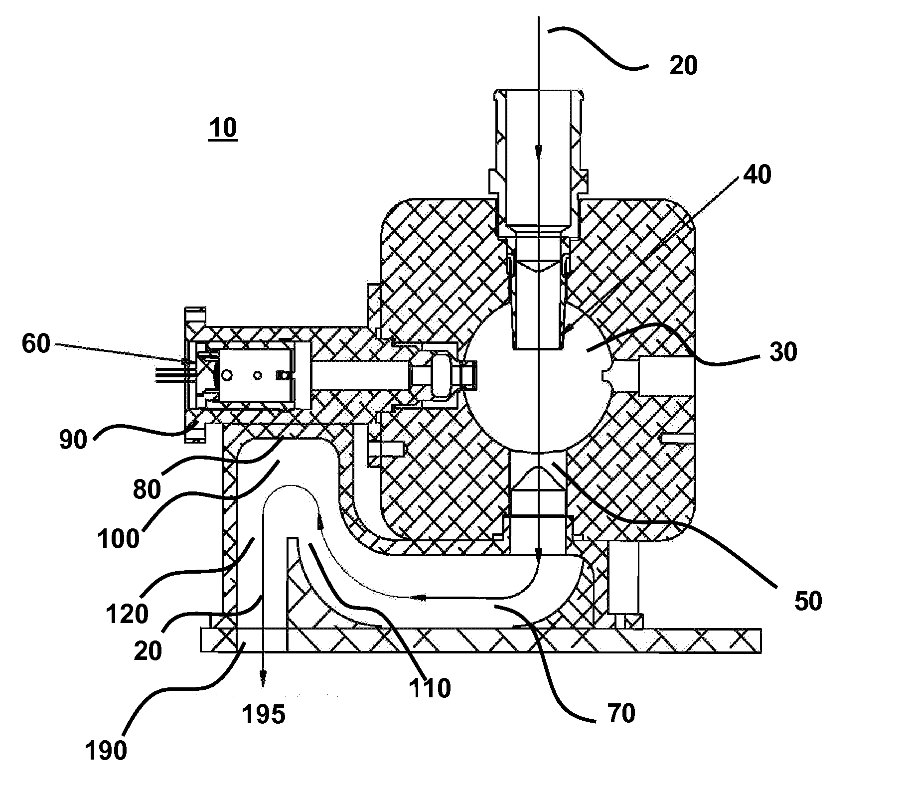
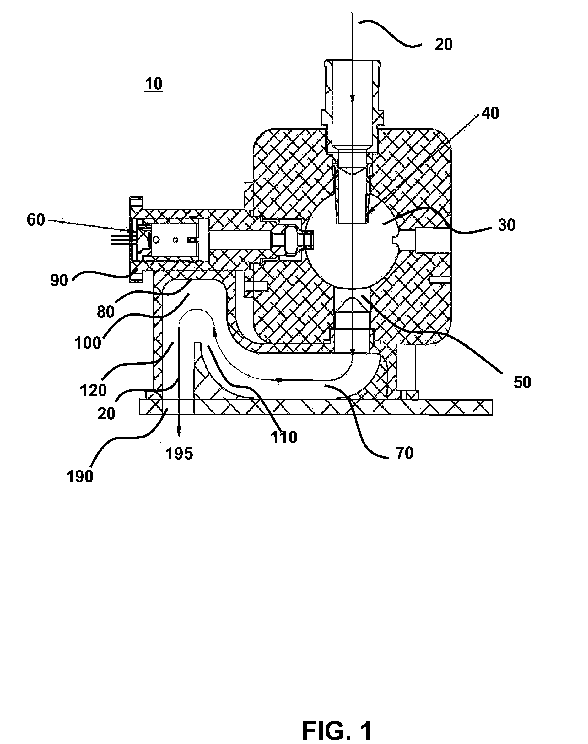
[0069]FIG. 1 is a schematic illustration of a particle sensor 10. Referring to FIG. 1, a fluid sample 20 is introduced to a sample chamber 30 at an inlet orifice 40. An optical source 60 illuminates fluid sample within chamber 30 and information is collected and analyzed to provide information about the status of fluid sample 20, as known in the art, such as scattering (forward and / or side), intensity, emission spectra, etc. Fluid sample flows out of the sample chamber 30 at an outlet orifice 50 and into outlet passage 70. Fluid sample exits the particle sensor 10 at an exhaust orifice or port 190. The general path of flowing fluid sample 20 is indicated by the arrow that transits the sample chamber 30 and outlet passage 70.

[0070]In this example, the outlet passage 70 further comprises a plenum 100 having a portion 80 in thermal contact with the optical source 60. In an embodiment, optical source 60 is positioned within the particle sensor 10 by a mounti...

example 2

Self-Contained Heat Sink Connected to Outlet Orifice

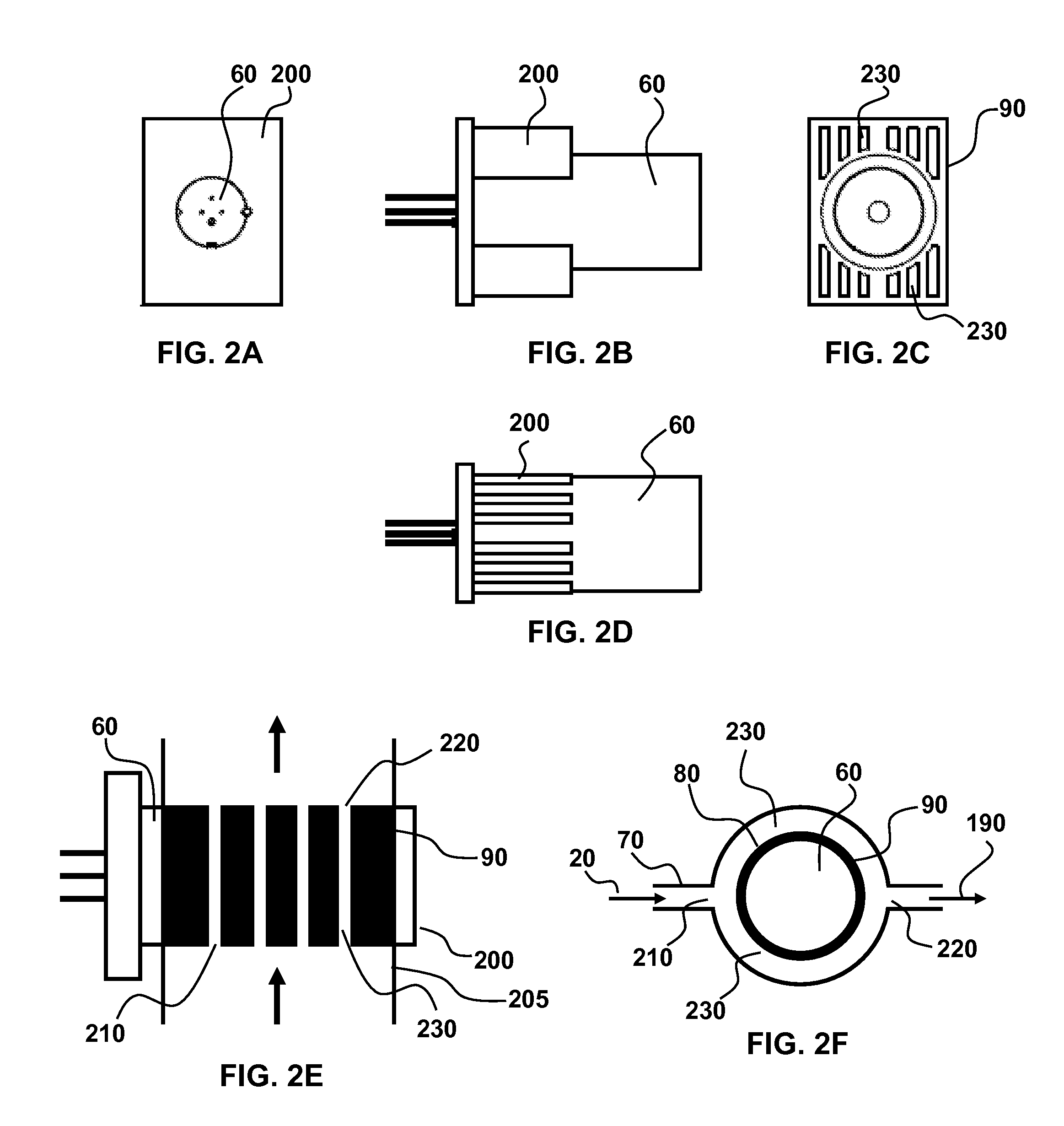
[0076]In an embodiment, a mounting element 90 with integral heat sink 200 provides cooling, (see, for example, FIGS. 2 and 5). A heat sink conduit 205 that provides sample fluid 20 to the heat sink 200 is connected to the sample chamber outlet orifice 50, the exhaust orifice 190, or to an outlet passage location between the outlet orifice 50 and exhaust orifice 190. To transport fluid sample to the heat sink, the heat sink passage is operably connected to the means for generating fluid flow, such as vacuum source or pump. In an aspect, the heat sink conduit comprises tubing, including flexible tubing, connected at one end for receiving sample fluid, such as to chamber outlet orifice 50, outlet passage 70 or exhaust orifice / port 190 and at the other end to inlet heat sink orifice 210 for introducing the fluid sample to the heat sink.

[0077]The heat sink optionally comprises one or more heat sink transfer passages 230 within the mount...

example 3

Airflow Cavity Within Mounting Assembly

[0080]An alternative cooling process relates to an airflow cavity positioned between the optical source 60 and optical source mount 90. In this aspect, air is routed into and out of the cavity using either tubing or a shaped air plenum. Although this aspect eliminates one thermal interface (e.g., the air coolant is in direct contact with the optical source), there is added complexity and cost that is minimized for the embodiments that use the sample fluid itself as the coolant. In this aspect, air is forced into the cavity by any means known in the art such as a fan or pump.


PUM

PropertyMeasurementUnit
power consumptionaaaaaaaaaa
operating temperatureaaaaaaaaaa
temperatureaaaaaaaaaa

Abstract

The invention relates to particle sensors that are capable of passively cooling high-powered optical sources within the sensor, thereby extending the optical source lifetime without requiring additional power. The sensor detects particles within a sample fluid by optical interaction of the optical source with flowing sample fluid in the sample chamber. Sample fluid that exits the sample chamber is directed into thermal contact with the optical source, thereby cooling the optical source. Sample fluid that has come into thermal contact with the optical source is continuously removed from the sensor to ensure the optical source is adequately cooled. A variety of elements are used to facilitate thermal contact between the optical source and sample fluid including plenums, heat sinks, and airflow cavities. Provided are related methods for cooling a one or more heat-producing device within a particle sensor.

Description

CROSS-REFERENCE TO RELATED APPLICATIONS[0001]This application claims the benefit under 35 U.S.C. 119(e) of U.S. Provisional Patent Application No. 60 / 896,649 filed on Mar. 23, 2007.BACKGROUND OF THE INVENTION[0002]The invention is generally in the field of optical particle sensing and provides systems and methods for cooling optical sources used in optical particle sensors. The cooling systems of the present invention substantially increase the operating life of optical sources, such as a laser, within the sensor and are relatively inexpensive and simple to incorporate into an optical particle sensor.[0003]Optical particle sensors and counters are useful in a variety of industrial applications where it is important that the purity of materials used in a process be continuously monitored. For example, in semi-conductor and other clean-room settings, or industries requiring sterile and pure production (e.g., pharmaceuticals), material fluids that are used to make the end product are c...

Claims


Application Information

Patent Timeline
Patent Type & Authority Applications(United States)
IPC IPC(8): G01N21/00G01N1/10
CPCG01N15/0205G01N2001/2282
Inventor MILLER, RICK
Owner PARTICLE MEASURING SYST
Why Eureka
Try Eureka