Display Element And Display Device

a display element and display device technology, applied in the field of display element and display device, can solve the problems of difficult to enhance high-speed responsivity to several milliseconds or less, difficult to bring precisely identical image quality depending on the angle of liquid crystal molecules, and high response time, and achieve excellent light utilization efficiency and low voltage driving

Inactive Publication Date: 2008-05-08
INOUE IICHIRO +3
View PDF21 Cites 44 Cited by
  • Summary
  • Abstract
  • Description
  • Claims
  • Application Information

AI Technical Summary

Benefits of technology

[0048]When a sufficiently high voltage is applied, the display element can exhibit, at the maximum, an optical anisotropy corresponding to the refractive index anisotropy Δn inherent in the molecules of the liquid crystalline medium in the nematic phase. Thus, it is possible to obtain a display element excellent in light utilization efficiency.
[0049]Therefore, in order to exhibit the optica...

Problems solved by technology

This makes it impossible to bring a precisely identical image quality depending upon angles at the liquid crystal molecules are viewed and directions from the liquid crystal molecules are viewed.
Additionally, all of the nematic liquid crystal display modes take advantage of the rotation of liquid crystal molecules with the application of an electric field, and require much time for response because the liquid crystal molecules rotate while orienting.
On this account, since several tens of milliseconds to several hundreds of milliseconds are unavoidably required for the response of bulk liquid crystal phases, it is difficult to enhance high-speed responsivity to several milliseconds or less.
For this reason, as far as the nematic liquid crystal display mode is used, it is difficult to realize the high-speed response property and the wide viewing angle property both of which are essential properties for the LCD-TV.
However, the smetic liquid crystal modes have not yet solved problems such as impact resistance and temperature characteristics and thus have not been developed for commercial use.
However, the PDLC mode has the problems such as a small difference in contrast between the dispersed state and transparent state and a high driving voltage, and thus have not been developed for commercial use.
A significant practical problem to be overcome for the utilization of the Kerr effect in display elements is that utilization of the Kerr effect requires a higher driving voltage compared with conventional liquid crystal display elements.
Another big problem i...

Method used


Image

  • Display Element And Display Device
  • Display Element And Display Device
  • Display Element And Display Device

Examples


Embodiment Construction

[0074]One embodiment of the present invention is described below with reference to FIG. 1 to FIG. 16(a) and FIG. 16(b).

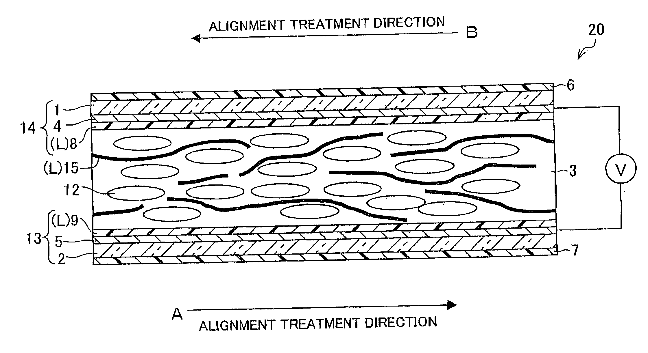
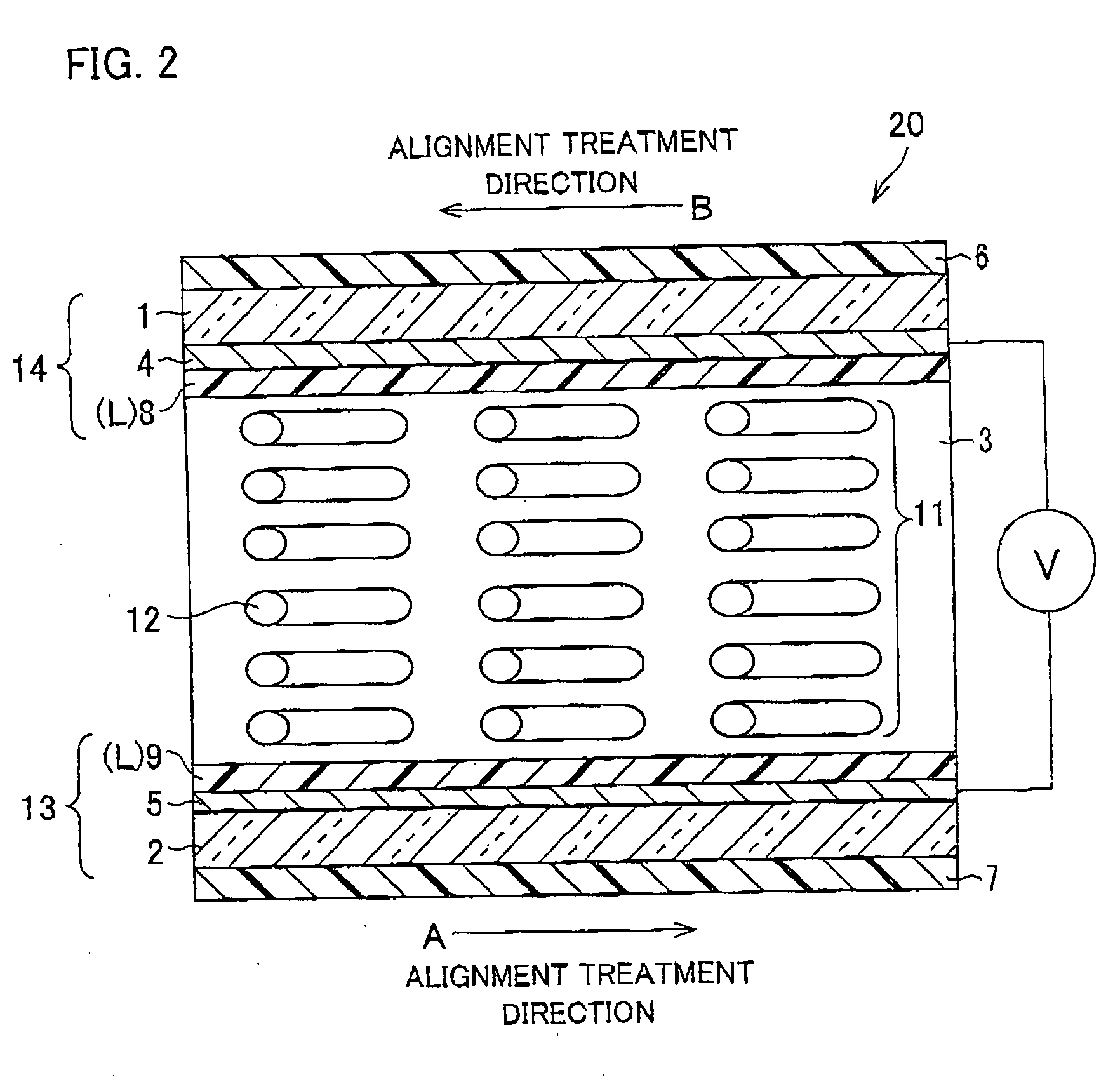
[0075]FIG. 2 is a cross-sectional diagram schematically illustrating the structure of a display element according to one embodiment of the present invention. FIG. 3 is a block diagram schematically illustrating the main part of the display device including the display element according to one embodiment of the present invention. FIG. 4 is a diagram schematically illustrating the periphery of the display element included in the display device illustrated in FIG. 3.

[0076]For use of a display element according to the present embodiment, the display element is provided in a display device, together with a drive circuit, a signal line (data signal line), a scanning line (scanning signal line), a switching element, and other components.

[0077]As illustrated in FIG. 3, a display device 100 according to the present embodiment includes: a display panel 102 having pixels 10 ar...


PUM

PropertyMeasurementUnit
Thicknessaaaaaaaaaa
Nanoscale particle sizeaaaaaaaaaa
Frequencyaaaaaaaaaa

Abstract

A display element of the present invention includes: a pair of substrates which are opposed to each other; and a substance layer, which is sandwiched between the substrates, exhibiting an optical isotropy when no electric field is applied, while exhibiting an optical anisotropy when an electric field is applied, and the display element performs display operation by applying an electric field to between the substrates. The substance layer includes a liquid crystalline medium exhibiting a nematic liquid crystal phase, and it is Δn×|Δ∈|≧1.9, where Δn is a refractive index anisotropy at 550 nm in a nematic phase of the liquid crystalline medium, and |Δ∈| is an absolute value of a dielectric anisotropy at 1 kHz in the nematic phase of the liquid crystalline medium. The display element and a display device including the display element realize a fast response speed and a low driving voltage and driving in a wide temperature range.

Description

TECHNICAL FIELD[0001]The present invention relates to a display element and a display device. Particularly, the present invention relates to a display element and a display device both of which is capable of driving at a low voltage and in a wide temperature range and have a wide viewing angle property and high-speed response property.BACKGROUND ART[0002]Among various kinds of display elements, a liquid crystal display element has the advantages of being thin, light, and consuming low power. For this reason, the liquid crystal display element has recently come into wide use in display devices incorporated in (i) office automation (OA) equipments such as word processor and personal computer, (ii) information terminals such as video camera, digital camera, and mobile phone, and others. Particularly, a liquid crystal display element using nematic liquid crystal was first used as a display element for numeric segment displays in a clock, an electronic calculator, and others, and has rec...

Claims


Application Information

Patent Timeline
IPC IPC(8): C09K19/02
CPCC09K19/22C09K19/24C09K19/3028C09K19/3068C09K19/3444C09K2019/3027C09K2019/0481G02F1/1334G02F1/13731G02F1/139G02F1/1393C09K2019/0407C09K19/02G02F1/1337
Inventor INOUE, IICHIROSHIBAHARA, SEIJIMIYACHI, KOICHIISHIHARA, SHOICHI
Owner INOUE IICHIRO
Why Eureka
Try Eureka