Air-cap mold structure that shortens molding cycle

A molding cycle and mold technology, applied in the field of air-cap mold structure, can solve the problems that the ejector system cannot meet the appearance requirements of the molded product, and the difficulty of ejecting the box molded product, so as to shorten the ejection time, shorten the molding cycle, and have a simple structure. Effect

Active Publication Date: 2021-04-06
深圳市三精模具有限公司
View PDF3 Cites 0 Cited by
  • Summary
  • Abstract
  • Description
  • Claims
  • Application Information

AI Technical Summary

Problems solved by technology

[0003] Aiming at the problems existing in the prior art, the main purpose of the present invention is to provide an air cap mold structure that shortens the molding cycle, aiming to solve the problem that the ejection system of the existing mold cannot meet the appearance requirements of the molded product, and the ejection of the box or shell Difficult problems when molding products

Method used


Image

  • Air-cap mold structure that shortens molding cycle
  • Air-cap mold structure that shortens molding cycle
  • Air-cap mold structure that shortens molding cycle

Examples


Embodiment Construction

[0018] The invention proposes an air cap mold structure which shortens the molding cycle.

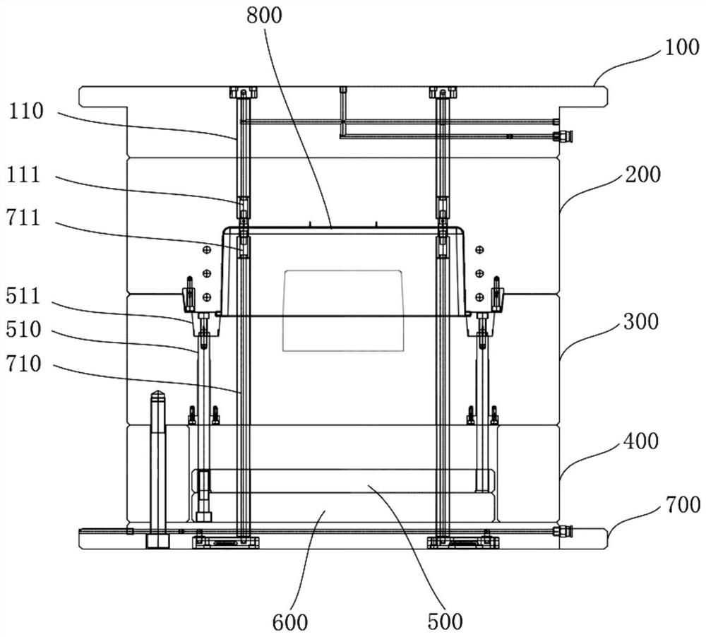
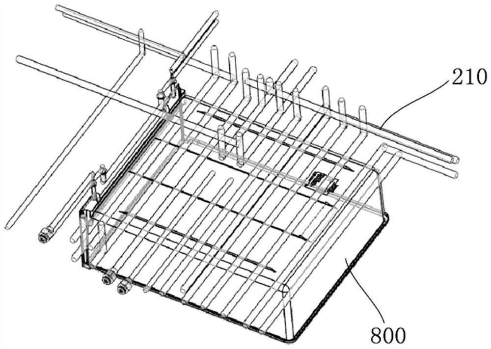
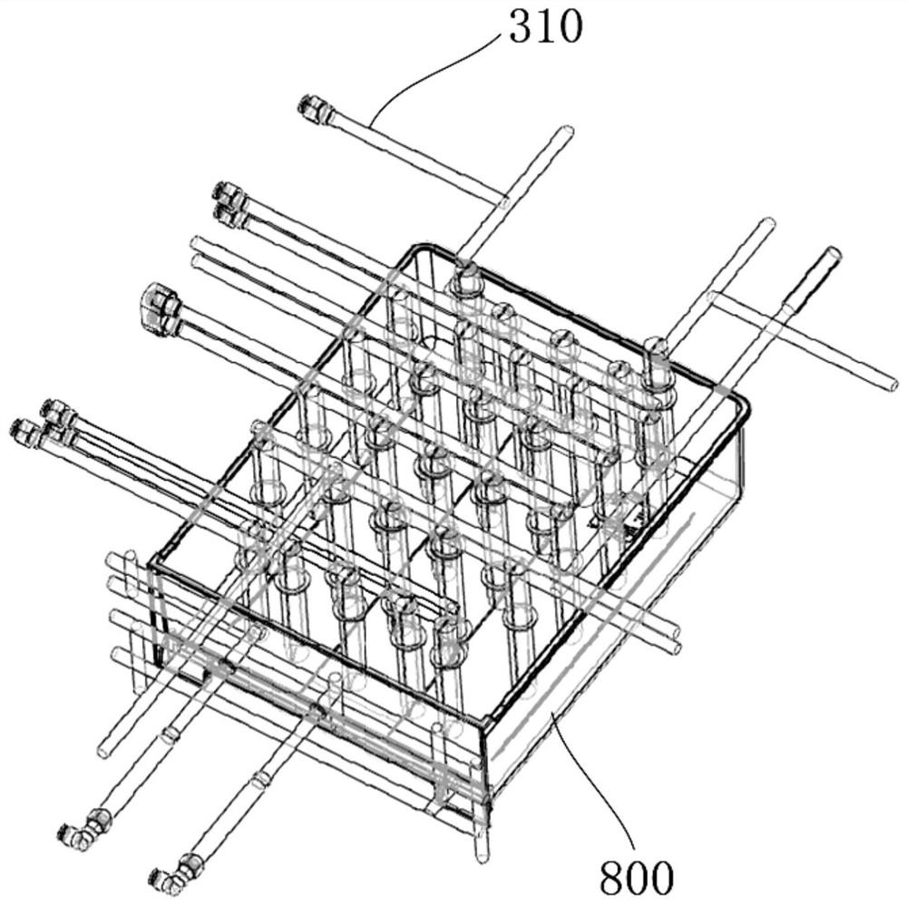
[0019] refer to Figure 1-5 , figure 1 It is a structural schematic diagram of an embodiment of an air-cap mold structure that shortens the molding cycle of the present invention, figure 2 It is a schematic structural diagram of the first cooling water circuit in an embodiment of the present invention, image 3 It is a schematic structural diagram of the second cooling water channel in an embodiment of the present invention, Figure 4 It is a schematic structural diagram of the first transverse gas path in an embodiment of the present invention, Figure 5 It is a schematic structural diagram of the second transverse gas path in an embodiment of the present invention.

[0020] Such as figure 1 As shown, in the embodiment of the present invention, the structure of the air-cap mold that shortens the molding cycle includes from top to bottom: a fixed mold seat plate 100, a fixed mold ...


PUM


Abstract

There is the first cooling water road, and there is a second cooling water road inside the dynamic template.It also includes a number of first vertical guidance rods and several second vertical width rods. The motion molding plate has the first horizontal air path. The fixed mold plate has a second horizontal air path.The top rod, the dynamic template is equipped with one -to -one top blocks.The beneficial effect of the present invention is that the structure is compact and simple and easy to install; the force is more uniform when the molding products are pushed out, and the accuracy is higher; when the mold is opened, the molding products are not easy to adhere to the fixed template, and the mold opening efficiency is more efficient.High, it is easier to top the molding products, shortening the top time, thereby greatly shortening the molding cycle.

Description

technical field [0001] The invention relates to the technical field of injection molds, in particular to an air cap mold structure which shortens the molding cycle. Background technique [0002] In daily life, many products use plastic products, such as cars, TVs, mobile phones, etc. These plastic products are all injection molded parts through mold injection molding. Some injection molded parts are structural parts installed inside the product, and some injection molded parts are It is the functional parts that play special functions in the product, and most of the injection molded parts are appearance parts installed outside the product. For these exterior molding products, transparent PP materials are often used for injection molding because of the aesthetic requirements for their exterior surfaces, and ejector pin marks are not allowed on the product surface. If the traditional ejector pin is used to eject the molded product, it cannot be achieved. Appearance requiremen...

Claims


Application Information

Patent Timeline
Patent Type & Authority Patents(China)
IPC IPC(8): B29C45/43B29C45/40
Inventor 宋磊何海欧
Owner 深圳市三精模具有限公司
Why Eureka
Try Eureka