Reverse drive separation front drive axle and half-shaft clutching device and control method thereof

A front drive axle, reverse transmission technology, applied in control devices, transportation and packaging, vehicle components, etc., can solve problems such as driving resistance, steering resistance, fuel consumption, etc., and achieve the effect of reducing vibration and fuel consumption.

Pending Publication Date: 2019-05-31
泉州市力普机械科技有限公司
View PDF0 Cites 4 Cited by
  • Summary
  • Abstract
  • Description
  • Claims
  • Application Information

AI Technical Summary

Problems solved by technology

[0002] At present, four-wheel drive is more and more widely used in trucks. The switch between four-wheel drive and two-wheel drive is realized by the fact that the transfer case does not output power to the front axle; when two-wheel drive, although the transfer case does not output power to the front axle, it is During the running of the truck, the front wheels still drive the three main transmission components of the front axle shaft, differential, and front drive shaft to passively rotate, which will cause some additional vibration, driving resistance, steering resistance, and fuel consumption.

Method used


Image

  • Reverse drive separation front drive axle and half-shaft clutching device and control method thereof
  • Reverse drive separation front drive axle and half-shaft clutching device and control method thereof
  • Reverse drive separation front drive axle and half-shaft clutching device and control method thereof

Examples


Embodiment 1

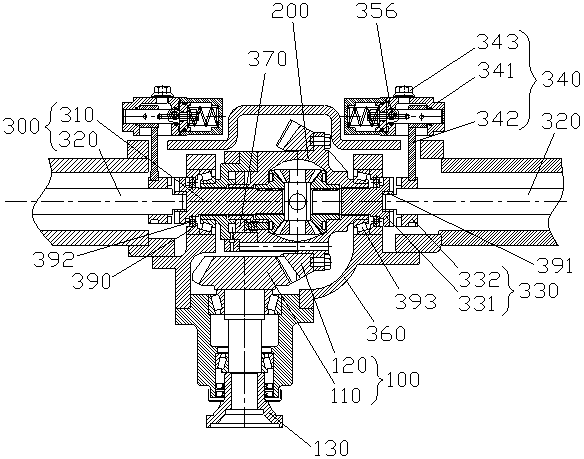
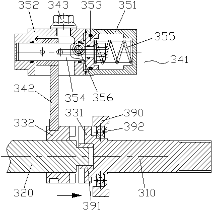
[0027] Embodiment one: if Figure 1~6 As shown, a reverse transmission separation front drive axle includes a final drive 100, a differential 200, two left and right axle shafts 300 and an axle housing 400, and the differential 200 includes a first sun gear 211, a second sun gear Gear 212, two planetary gears 220, cross shaft 230, first half shell 241 and second half shell 242, the first sun gear 211 and second sun gear 212 are respectively fixedly installed on the inner ends of two half shafts 300 The half shaft 300 includes an inner half shaft 310 for connecting the differential 200 and an outer half shaft 320 for connecting the hub 500, the inner end of the outer half shaft 320 is free from the outer end of the inner half shaft 310 Rotationally connected, the inner end of the outer half shaft 320 and the outer end of the inner half shaft 310 are provided with a half shaft clutch 330 for controlling power cut-off and transmission between the two, the control of the half shaf...

Embodiment 2

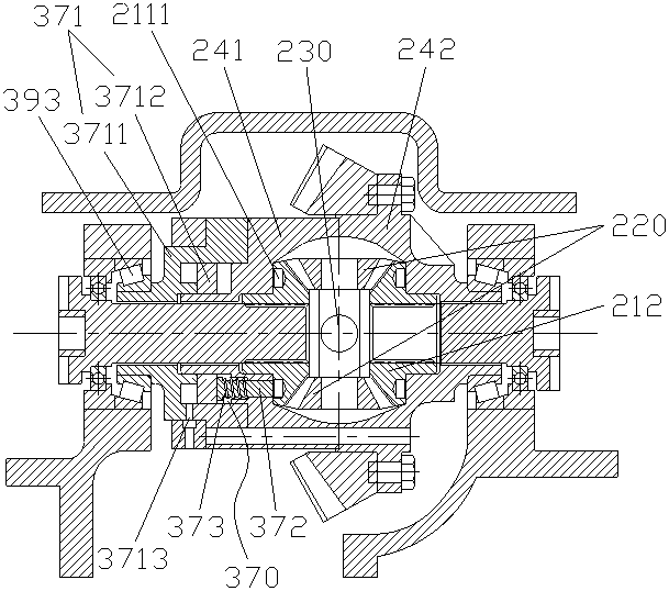
[0039] Embodiment two: if Figure 1~6 As shown, a reverse drive separation front drive axle differs from Embodiment 1 in that it further includes a differential lock 370 installed on the differential 200 .

[0040] In the second embodiment, the differential lock 370 includes a second cylinder 371, a pin 372 and a second return spring 373, the second cylinder 371 includes a second cylinder 3711 and a second piston 3712, the first The second cylinder body 3711 is fixedly connected with the first half shell 241 and encloses a sliding chamber, the side wall of the second cylinder body 3711 is provided with a second air inlet 3713 communicating with the sliding chamber, and the second piston 3712 slides Installed in the sliding cavity, the first half-shell 241 is provided with a concentric and connected spring seat hole and a pin hole, the head of the pin 372 is in contact with the second piston 3712, and the tail of the pin 372 passes through in turn. Through the spring seat hole...

Embodiment 3

[0043] Example 3: Please refer to Figure 1~5 , a half-shaft clutch device for reverse transmission separation of the front drive axle, including a half-shaft 300, the half-shaft 300 includes an inner half-shaft 310 for connecting the differential 200 and an outer half-shaft 320 for connecting the wheel hub 500, The inner end of the outer half-shaft 320 is freely rotatably connected to the outer end of the inner half-shaft 310, and a device is provided between the inner end of the outer half-shaft 320 and the outer end of the inner half-shaft 310 to control the distance between the two. Half shaft clutch 330 for power cut-off and transmission.

[0044] In the third embodiment, the half-shaft clutch 330 is preferably but not limited to a jaw clutch. The jaw clutch is a clutch that relies on the teeth on the end face to embed or disengage each other to transmit or cut off the movement, and has a simple structure. , small size, large transmission torque, convenient operation, et...


PUM


Abstract

The invention discloses a reverse drive separation front drive axle and a half-shaft clutching device and control method thereof. The reverse drive separation front drive axle comprises a main speed reducer, a differential mechanism, a left half-shaft, a right half-shaft and an axle housing, wherein the half-shafts comprise inner half-shafts used for being connected with the differential mechanismand outer half-shafts used for being connected with a wheel hub, and half-shaft clutches used for controlling the power cutoff and transmission between the inner ends of the outer half-shafts and theouter ends of the inner half-shafts are arranged between the inner ends of the outer half-shafts and the outer ends of the inner half-shafts; when four drive is needed, through the connection of thehalf-shaft clutches, the inner ends of the outer half-shafts of the front drive axle are connected with the outer ends of the inner half-shafts to achieve the power transmission of the front drive axle; when two drive is needed, through the separation of the half-shaft clutches, the inner ends of the outer half-shafts of the front drive axle are disconnected with the outer ends of the inner half-shafts to achieve the power cutoff of the front drive axle. The reverse drive separation front drive axle and the half-shaft clutching device and control method thereof have the advantages that the power connection between the inner half-shafts and the outer half-shafts is cut off when the two drive is needed through the half-shaft clutches, so that tires rotate freely on the front axle to achievethe purposes of reducing vibration and reducing fuel consumption.

Description

technical field [0001] The invention belongs to the technical field of front drive axles, and in particular relates to a reverse drive separation front drive axle, a half shaft clutch device and a control method thereof. Background technique [0002] At present, four-wheel drive is more and more widely used in trucks. The switch between four-wheel drive and two-wheel drive is realized by the fact that the transfer case does not output power to the front axle; when two-wheel drive, although the transfer case does not output power to the front axle, it is During the running of the truck, the front wheels still drive the three main transmission components of the front axle shaft, differential, and front drive shaft to passively rotate, which will cause some additional vibration, driving resistance, steering resistance, and fuel consumption. Contents of the invention [0003] In view of the deficiencies in the prior art, the technical problem to be solved by the present invent...

Claims


Application Information

Patent Timeline
Patent Type & Authority Applications(China)
IPC IPC(8): B60K17/02B60K17/08B60K17/16
Inventor 邱恒基林节来
Owner 泉州市力普机械科技有限公司
Why Eureka
Try Eureka