Plate cutting device

A technology for cutting and paneling, applied in auxiliary sawing devices, woodworking safety devices, sawing components, etc., can solve the problems of potential safety hazards, increased costs, and slow speed of panel saws

Inactive Publication Date: 2019-06-04
陈宙清
View PDF1 Cites 0 Cited by
  • Summary
  • Abstract
  • Description
  • Claims
  • Application Information

AI Technical Summary

Problems solved by technology

In the above-mentioned patent application, the saw blade also only has the function of height adjustment, and can only saw straight grooves, but cannot saw inclined grooves. Panel saws are mainly used for cutting various panels in furniture manufacturing and wood products industries. Most of the saws are semi-automatic. Although this kind of panel saw can also cut the board, the speed of this kind of panel saw is slow, the processing efficiency is low, the labor intensity of the operator is high, and the cost is increased. The board is fed from the position of the pressing device at the left end of the frame, after positioning, pressing, and then cutting, and then discharged from the feeding position after processing. This kind of feeding and discharging are at the same position, which is very easy to operate. Convenience, not only affects the processing progress, but also affects the product processing accuracy, and there are potential safety hazards. The application number is 200420044748.3, which is an electronic panel saw with adjustable saw blades. Although the electronic panel saw with this structure can make the saw body Tilting can be used to saw oblique grooves, and at the same time, it has a simple structure and is easy to operate, but it does not have the function of a fixing frame, no electric fan and lighting, and lacks versatility

Method used


Image

  • Plate cutting device
  • Plate cutting device
  • Plate cutting device

Examples


Embodiment Construction

[0014] In order to make the technical means, creative features, goals and effects achieved by the present invention easy to understand, the present invention will be further described below in conjunction with specific embodiments.

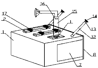
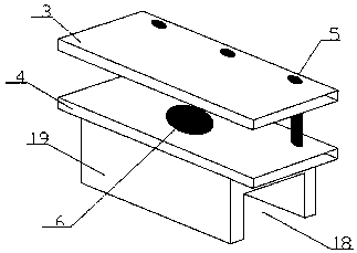
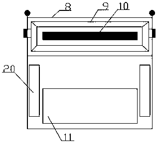
[0015] Such as figure 1 , figure 2 and image 3 As shown, a panel cutting device includes an electronic panel saw body 1, a fixed frame 17 and a door body 8, the top of the electronic panel saw body 1 is provided with two parallel protrusions 2, and the fixed frame 17 includes Upper fixed piece 3, lower fixed piece 4, tightening bolt 5 and slide block 19, described slide block 19 is fixedly connected on the bottom of described lower fixed piece 4, between described upper fixed piece 3 and described lower fixed piece 4 The fastening bolts 5 are detachably connected together, the bottom of the slider 19 is provided with a groove 18, and the fixing frame 17 is slidably connected to the protrusions 2 and each protrusion 2 is provided with two fixed...


PUM


Abstract

The invention discloses a plate cutting device, and relates to the field of industrial automation. The plate cutting device comprises an electronic cut-to-size saw body, a fixing frame and a door body. Two parallel protrusions are arranged at the top of the electronic cut-to-size saw body, and the fixing frame comprises an upper fixing piece, a lower fixing piece, a tightening bolt and a sliding block. The upper fixing piece and the lower fixing piece are detachably connected by the tightening bolt, the fixing frame is slidably connected to the protrusions, and suction cups are arranged at thebottom of the upper fixing frame and the top of the lower fixing frame. The electronic cut-to-size saw body is internally provided with a cavity body, the door body is rotatably connected to the electronic cut-to-size saw body, the door body is provided with a plate member, and an illumination lamp is arranged on one side of the plate member. The fixing frame can slide on the protrusions, the position of a plate can be conveniently adjusted, the fixing frame can conveniently fix plates of different thicknesses, the suction cups further fasten the plate, stuff can be placed in the cavity body,the door body can realize the opening and closing functions of the cavity body, and the illumination lamp can realize the function of night illumination.

Description

technical field [0001] The invention relates to the field of industrial automation, in particular to a plate cutting device. Background technique [0002] The adjustment of the saw blade of the electronic panel saw in the prior art generally only has the function of height adjustment, that is, generally only the shaft seat of the saw blade is connected by the cylinder, and the height of the saw blade is adjusted by driving the shaft seat up through the cylinder. For example, the patent application number is . The application date is year, month, day, and the patent name of the invention is a vertical panel saw, which includes a frame with a panel, horizontal gauges mounted on the panel, a saw shaft motor connected to the saw shaft, and a saw shaft connected to the saw blade. The utility model is characterized in that the frame adopts a vertical frame, guide gauges are mounted on the vertical frame, a saw shaft elevating drive device is mounted on the guide gauge, and the bas...

Claims


Application Information

Patent Timeline
Patent Type & Authority Applications(China)
IPC IPC(8): B27G19/00
Inventor 陈宙清
Owner 陈宙清
Why Eureka
Try Eureka