Floating roller friction driving device

A friction drive, roller technology, applied in transportation and packaging, conveyors, mechanical conveyors, etc., can solve the problems of low equipment precision requirements, high equipment maintenance frequency, low production efficiency, etc., to achieve convenient equipment maintenance, Simple structure and stable operation

Pending Publication Date: 2019-06-04
DONGFENG DESIGN INST
View PDF10 Cites 0 Cited by
  • Summary
  • Abstract
  • Description
  • Claims
  • Application Information

AI Technical Summary

Problems solved by technology

[0002] With the rapid development of the automobile industry, large skateboards have been widely used as conveying devices for automobile production and assembly. The roller friction drive device, which is the main power source of large skateboards, has low equipment accuracy and cannot fully meet the installation accuracy requirements of the driving position of the skateboard. , leading to serious wear of the rollers, insufficient driving force, high frequency of equipment maintenance, and low production efficiency. Therefore, an economical, reliable, stable and durable roller friction drive device is designed to reduce the failure rate of the production line and improve the assembly cycle of the skateboard production line. and efficiency are extremely important

Method used


Image

  • Floating roller friction driving device
  • Floating roller friction driving device
  • Floating roller friction driving device

Examples


Embodiment Construction

[0024] The present invention will be further described in detail below in conjunction with the accompanying drawings and specific embodiments.

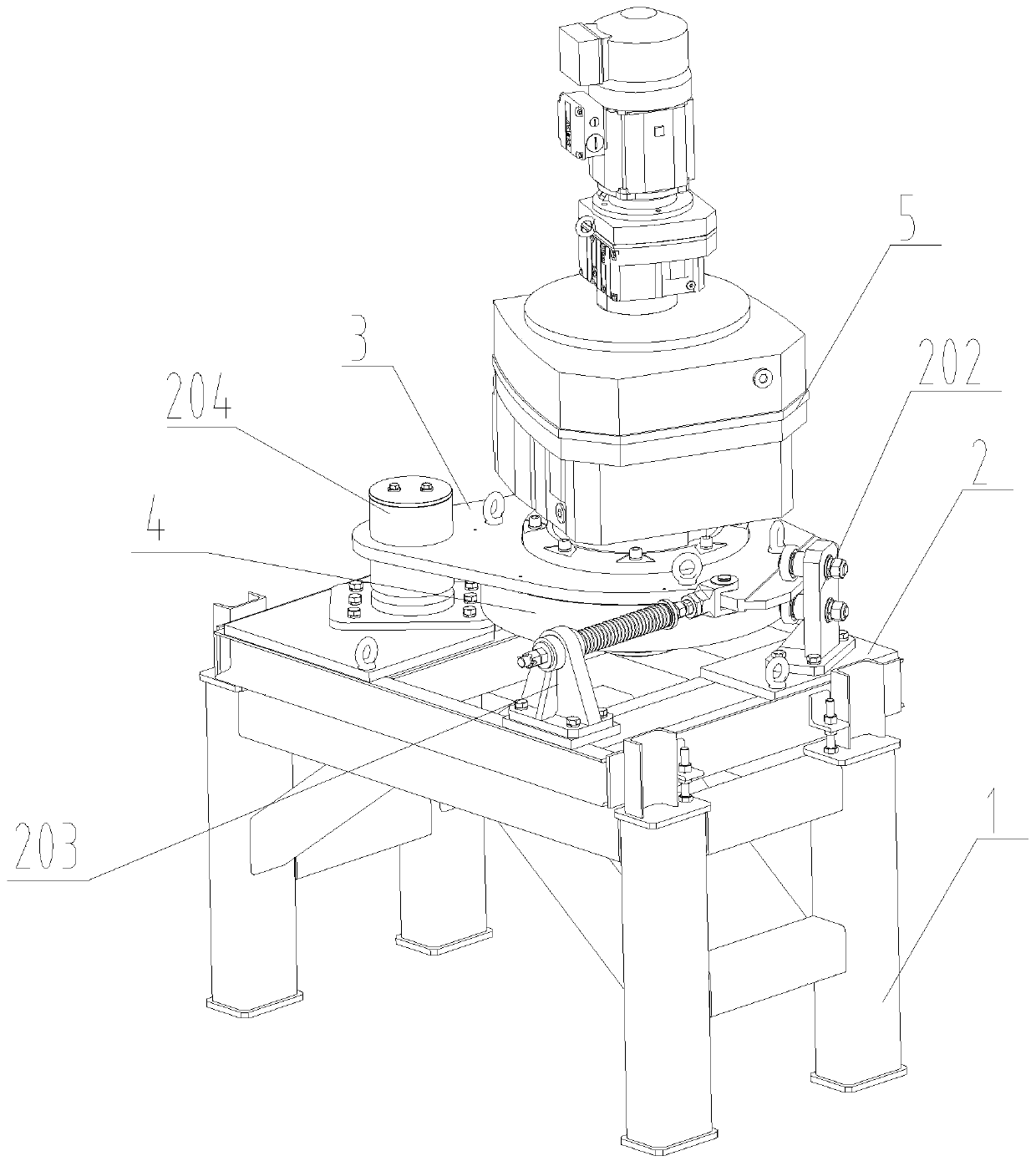
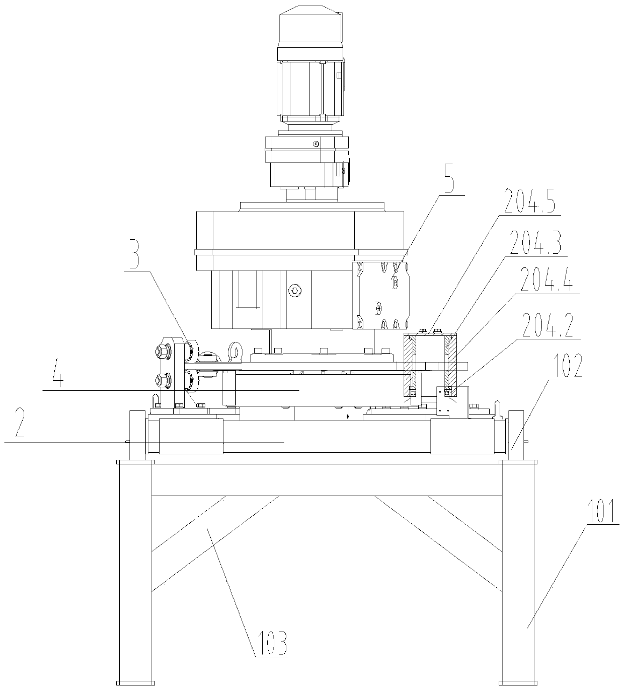
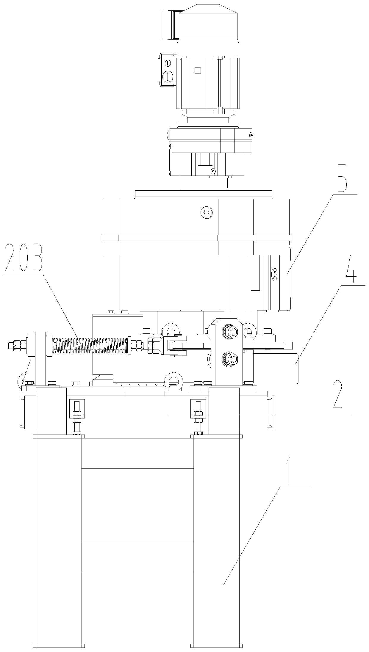
[0025] Such as figure 1 As shown in —9, the floating roller friction drive device mainly includes a bottom bracket 1, a support frame 2, a floating motor disc 3, a friction drive wheel 4, and a drive motor 5. The bottom bracket 1 is fixed above the pit or the steel platform, and the support frame 2 is fixed above the bottom bracket 1 through frame fixing screws 201 . The floating motor disc 3 is installed between the drive motor 5 and the friction drive wheel 4 and fixed above the flange of the drive motor 5 . The bottom bracket 1 is composed of supporting legs 101 and limiting channel steel 102. Diagonal braces 103 are connected between the supporting legs 101. The limiting channel steel 102 is welded around the supporting legs 101 to become the installation limiting reference of the supporting frame 2. The supporting legs 101 can ...


PUM


Abstract

The invention discloses a floating roller friction driving device. The floating roller friction driving device comprises a motor driving structure. The motor driving structure is installed on a floating motor disc; the floating motor disc is located on the upper part of a supporting framework, the supporting framework is provided with a rotating shaft assembly hinged to the floating motor disc, asupporting wheel assembly capable of maintaining stable in the rotating process of the floating motor disc, and a tensioning rod assembly capable of maintaining the tensioning state between a frictiondriving wheel and a sliding plate. When the sliding plate makes a contact with the friction driving wheel, the tensioning rod assembly extrudes the friction driving wheel, the friction driving wheelcan tightly tangent to the outer side of a large sliding plate, then the friction driving wheel is driven to rotate by the driving motor through pressing force of the friction driving wheel, when thepressing force of the friction driving wheel is too large, the friction driving wheel is driven by the floating motor disc to swing on the supporting wheel assembly, thus the pressing force is adjusted and compensated, the pressing force of a driving device on the large sliding plate can be effectively controlled, and abrasion to the friction driving wheel is reduced.

Description

technical field [0001] The invention relates to the technical field of mechanized transportation of automobile production lines, in particular to a floating roller friction drive device. Background technique [0002] With the rapid development of the automobile industry, large skateboards have been widely used as conveying devices for automobile production and assembly. The roller friction drive device, which is the main power source of large skateboards, has low equipment accuracy and cannot fully meet the installation accuracy requirements of the driving position of the skateboard. , leading to serious wear of the rollers, insufficient driving force, high frequency of equipment maintenance, and low production efficiency. Therefore, an economical, reliable, stable and durable roller friction drive device is designed to reduce the failure rate of the production line and improve the assembly cycle of the skateboard production line. and efficiency are extremely important. Co...

Claims


Application Information

Patent Timeline
Patent Type & Authority Applications(China)
IPC IPC(8): B65G35/00
Inventor 宋泰宇任泽兵邹文泉许进敏张英张可徐克明
Owner DONGFENG DESIGN INST
Why Eureka
Try Eureka