An automatic riser clamping tool

A technology for clamping tooling and removing risers, which is applied in the field of automatic riser-removing clamping tools, can solve problems such as the lack of universality of the riser-removing mechanism, and achieve the effects of avoiding deformation, preventing crushing, and reducing rebound

Active Publication Date: 2017-01-04
广东戴卡旭汽车零部件有限公司
View PDF5 Cites 0 Cited by
  • Summary
  • Abstract
  • Description
  • Claims
  • Application Information

AI Technical Summary

Problems solved by technology

Even some products cannot be positioned by stoppers, resulting in the lack of versatility of the above-mentioned riser removing mechanism

Method used


Image

  • An automatic riser clamping tool
  • An automatic riser clamping tool
  • An automatic riser clamping tool

Examples


Embodiment Construction

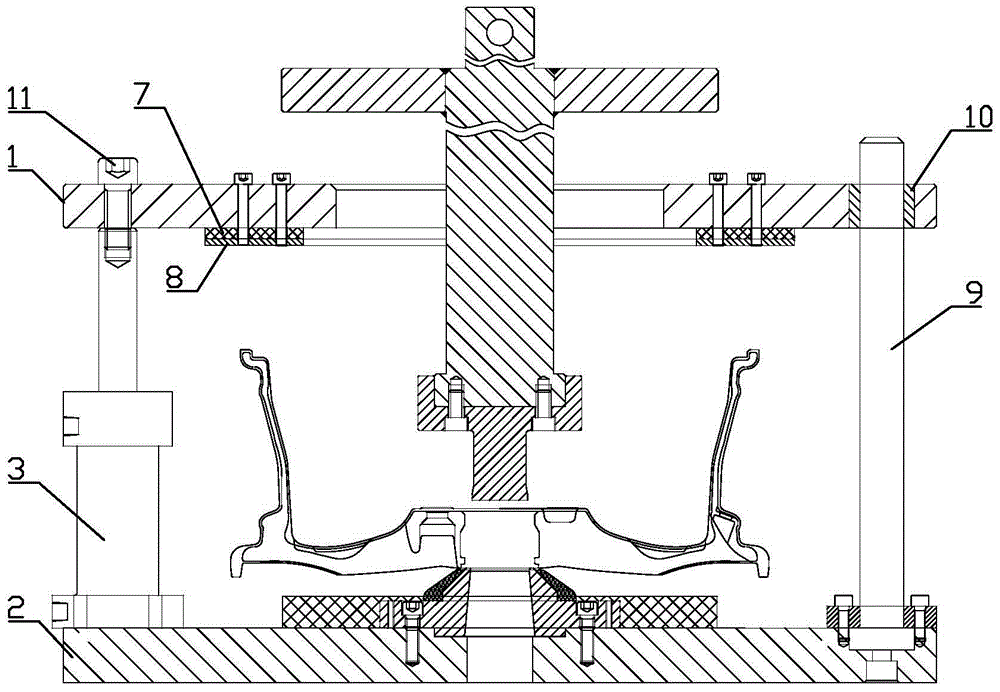
[0018] Such as figure 2 The automatic de-riser clamping tool shown includes clamping device and hydraulic system.

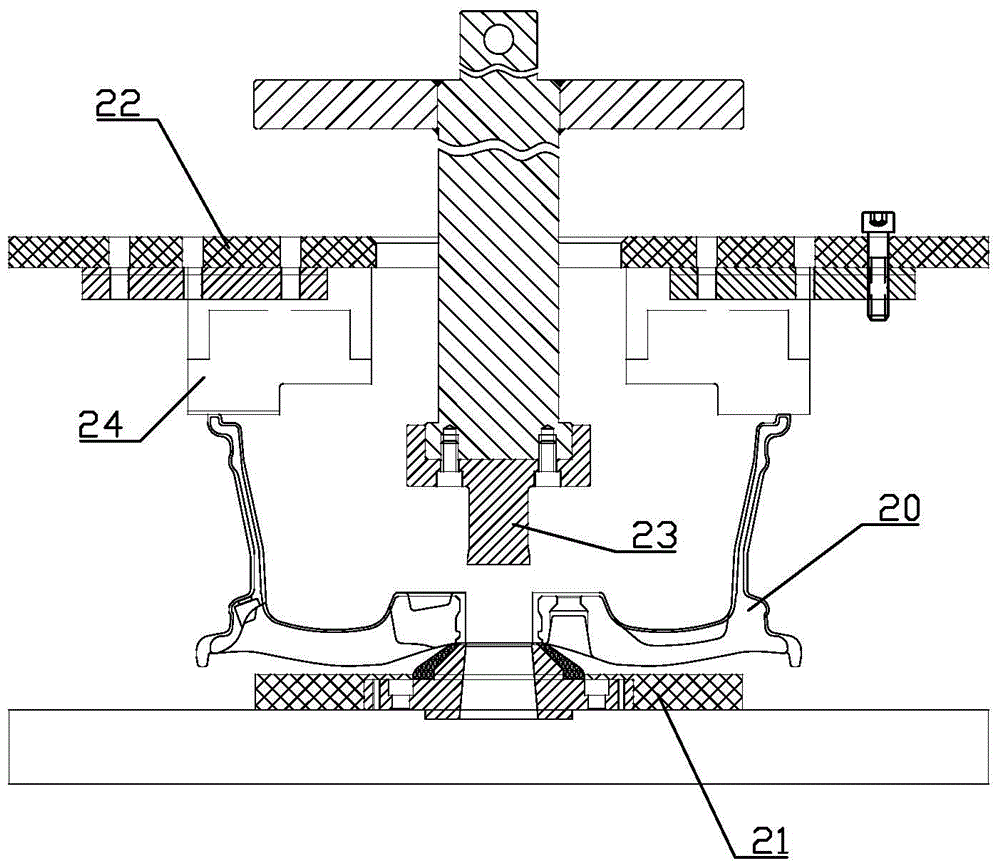
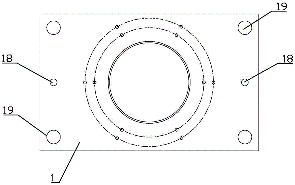
[0019] Wherein the clamping device includes an upper template 1 and a base 2 . The base 2 is fixed, and the hub is placed on the base 2 . The upper template 1 is above the base 2, which is rectangular and can move up and down relative to the base 2. There is a round hole in the middle of the rectangle. The punch of the punching machine can pass through the round hole, so as to raise the hub under the upper template 1. punching. The bottom of the upper template 1 is equipped with a pressing unit for pressing the rear rim of the wheel hub.

[0020] The base 2 is provided with two two-way oil cylinders 3, and each two-way oil cylinder 3 is symmetrically arranged on the left and right with respect to the center of the upper formwork 1, and the corresponding output shafts of each two-way oil cylinder 3 are fixedly connected to the left and right sides of the middl...


PUM


Abstract

The invention relates to an automatic riser clamping tool, which includes a clamping device and a hydraulic system. The clamping device includes an upper template and a base. The bottom of the upper template is equipped with a pressing unit. The system includes a first oil pipe and a second oil pipe. The oil return port of each two-way oil cylinder is connected in parallel with the first oil pipe, and the oil inlet is respectively connected in parallel with the second oil pipe. The first oil pipe is connected with a pressure switch. The invention utilizes a hydraulic system to synchronously control two two-way oil cylinders to smoothly drive the lower pressing unit of the upper formwork to move downward and press the rear rim of the wheel hub. There is no gap between the product and the lower pressing unit, which greatly reduces the riser The rebound of the product during punching can avoid the deformation of the product. At the same time, a pressure switch is installed at the oil return port of the two two-way oil cylinders to effectively control the pressing force of the hub and prevent crushing. The invention can be applied to remove the riser of the wheel hub.

Description

technical field [0001] The invention relates to the processing of auto parts, in particular to an automatic riser removal and clamping tool. Background technique [0002] At present, the punching of the central riser of the automobile wheel hub is generally carried out in a punching machine. The commonly used structures for removing the riser are as figure 1 shown. The hub 20 is placed above the base 21 , and above the hub 20 is a fixed template 22 , and a hole is opened in the center of the template 22 for passing a punch 23 . A stopper 24 is provided on the lower end surface of the template 22 to position the hub. For products with different sizes, the stopper 24 needs to be moved left and right to adapt, so there is a certain gap between the stopper and the hub. However, the thickness of the wheel core of the product is relatively large, and the rebound force of the product is also large during the process of flushing the riser. The existence of the gap causes a large ...

Claims


Application Information

Patent Timeline
Patent Type & Authority Patents(China)
IPC IPC(8): B21D28/04
Inventor 罗勇喻志辉蔡岳明谷明路
Owner 广东戴卡旭汽车零部件有限公司
Why Eureka
Try Eureka