
A grinding device for the inner wall of metal pipe fittings

A technology of metal pipe fittings and grinding discs, which is applied in the direction of grinding drive devices, metal processing equipment, grinding machines, etc., can solve the problems of poor adaptability and low efficiency, and achieve the effects of good protection, reduced impact damage, and high processing efficiency

Active Publication Date: 2022-05-17
南通佰瑞利电动工具有限公司
View PDF9 Cites 0 Cited by
  • Summary
  • Abstract
  • Description
  • Claims
  • Application Information

AI Technical Summary

Problems solved by technology

[0004] Aiming at the deficiencies of the prior art, the present invention provides a grinding device for the inner wall of metal pipe fittings, which solves the problem that usually a single grinding device can only grind a single pipe diameter when grinding pipe fittings in metal processing, and has poor adaptability. And only a single pipe can be polished, the problem of low efficiency

Method used


Image

  • A grinding device for the inner wall of metal pipe fittings
  • A grinding device for the inner wall of metal pipe fittings
  • A grinding device for the inner wall of metal pipe fittings

Examples


Embodiment 1

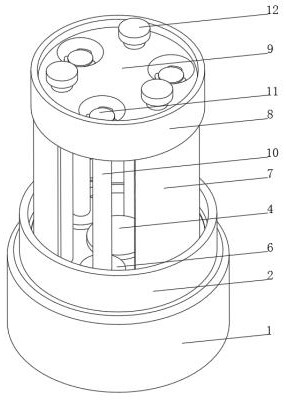
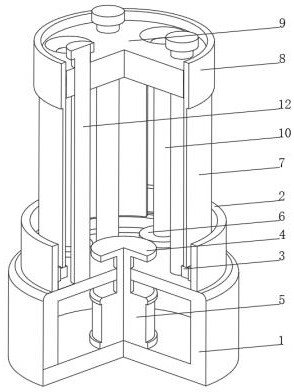
[0035] see Figure 1-4 , the present invention provides a technical solution: a grinding device for the inner wall of a metal pipe fitting, specifically comprising:

[0036] A fixed base 1, the top of the fixed base 1 is fixedly connected with a retaining ring 2, the inner wall of the retaining ring 2 is slidably connected with an inner gear ring 3 through an annular slideway, and the top of the fixed base 1 is fixedly connected with a limit rod 12;

[0037]Drive gear 4, the drive gear 4 is arranged inside the retaining ring 2, the drive shaft of the drive motor 5 is fixedly connected to the bottom of the drive gear 4, the drive motor 5 is arranged inside the fixed base 1, and the side of the drive gear 4 is meshed with a driven gear 6, The side of the driven gear 6 away from the drive gear 4 meshes with the inner wall of the ring gear 3;

[0038] Arc-shaped rotating plate 7, the bottom of the arc-shaped rotating plate 7 meshes with the top of the ring gear 3, the top of the ...

Embodiment 2

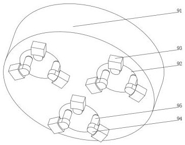
[0046] see Figure 1-5 On the basis of Embodiment 1, the present invention provides a technical solution: the grinding device 11 includes a grinding disc 111, the side of the grinding disc 111 is provided with a chute 112, and the inner wall of the chute 112 is slidably connected with a sliding rod 113, and the sliding rod 113 and the sliding rod 113 are connected to each other. A telescopic spring 114 is arranged between the inner walls of the grooves 112, and one end of the sliding rod 113 extends to the outside of the chute 112 and is fixedly connected with a grinding head 115, the side of the grinding head 115 is provided with a mounting groove 116, and the inner wall of the mounting groove 116 is rotatably connected with a hexagonal grinding rod 117 , the bottom of the grinding disc 111 is fixedly connected with the top of the rotating rod 10, the chute 112 is provided with multiple groups and is evenly distributed on the side of the grinding disc 111, the grinding head 11...


PUM


Abstract

The invention discloses a grinding device for the inner wall of a metal pipe fitting, which specifically comprises: a fixed base, the top of which is fixedly connected with a retaining ring, the inner wall of the retaining ring is slidably connected with an inner gear ring through an annular slideway, and the top of the fixed base is fixed connected to the limit rod; the drive gear, the drive gear is set inside the retaining ring, the drive shaft of the drive motor is fixedly connected to the bottom of the drive gear, the drive motor is set inside the fixed base, and the side of the drive gear is meshed with a driven gear, the side of the driven gear away from the driving gear meshes with the inner wall of the ring gear; the arc-shaped rotating plate, the bottom of the arc-shaped rotating plate meshes with the top of the ring gear, and the top of the arc-shaped rotating plate is fixedly connected with a rotating ring , The present invention relates to the technical field of metal processing. The inner wall grinding device of the metal pipe fittings can simultaneously polish multiple sets of pipe fittings, has high processing efficiency, can perform secondary grinding on the inner walls of the pipe fittings, and has a good grinding effect.

Description

technical field [0001] The invention relates to the technical field of metal processing, in particular to a grinding device for the inner wall of a metal pipe fitting. Background technique [0002] Metal processing, referred to as metalworking, refers to the production activities that humans process metal elements or materials with metal characteristics mainly composed of metal elements. It is a process technology that processes metal materials into articles, parts, and components, including bridges. It is widely used in different fields such as science, industry, art, handicrafts, etc. At present, when grinding pipe fittings in metal processing, usually a single grinding device can only grind a single pipe diameter, which has poor adaptability, and can only grind a single pipe material, with low efficiency. Contents of the invention [0003] (1) Solved technical problems [0004] Aiming at the deficiencies of the prior art, the present invention provides a grinding devi...

Claims


Application Information

Patent Timeline
Patent Type & Authority Patents(China)
IPC IPC(8): B24B5/40B24B27/00B24B41/06B24B49/00B24B49/16B24B47/12
CPCB24B5/40B24B27/0076B24B41/067B24B49/006B24B49/16B24B47/12Y02P70/10
Inventor 季威威
Owner 南通佰瑞利电动工具有限公司
Learn More