Non-lethal wireless stun projectile system for immobilizing a target by neuromuscular disruption

a wireless stun projectile and target technology, applied in the direction of musical toys, toys, weapons, etc., can solve the problem of incapacity of living objects, and achieve the effect of reducing the momentum associated and reducing the impact damage to the targ

Inactive Publication Date: 2013-01-01
SECURITY DEVICES INT INC
View PDF13 Cites 12 Cited by
  • Summary
  • Abstract
  • Description
  • Claims
  • Application Information

AI Technical Summary

Benefits of technology

[0020]According to the teachings of the present invention there is provided a wireless projectile for stunning a target including: an impact reduction subsystem to protect the target from impact damage caused by impact of the projectile onto the target, an attachment mechanism to secure the wireless projectile to the target upon impact of the wireless projectile upon the target and an energy delivery subsystem that supplies energy to the target thereby stunning the target after the wireless projectile is secured to the target by the attachment mechanism.
[0025]According to still further features in the described preferred embodiments, the wireless projectile includes a stability wing, which creates drag, slowing the projectile and preventing impact damage to the target. The stability wing further supplies aerodynamic stability so that the ballistic of the projectile remains flat as much as possible even at reduced velocity.
[0031]According to still further features in the described preferred embodiments, the impact reduction subsystem of the projectile includes a deformable pad. The deformable pad is located on an impact zone of the wireless projectile. Upon impact with a target, the pad deforms and spreads the energy of impact in space and time, preventing impact damage to the target.
[0037]According to still further features in the described preferred embodiments, the projectile includes a mobile subassembly and further includes an energy absorbing connection. The energy absorbing connection cushions deceleration of the mobile subassembly and reduces the force of impact of the projectile upon a target.
[0039]According to still further features in the described preferred embodiments, the impact reduction subsystem includes a sub-projectile. The sub-projectile impacts the target separately from an impact zone on the projectile body. Thereby the mass associated with the impact zone of the projectile body is reduced (because the projectile body does not include those components mounted in the sub-projectile; therefore their mass does not contribute to the force of impact of the projectile body). Thereby reducing the momentum associated with the impact zone, which reduces impact damage to the target.

Problems solved by technology

The electrical pulses cause neuromuscular-disruption, which incapacitates a living object.

Method used


Image

  • Non-lethal wireless stun projectile system for immobilizing a target by neuromuscular disruption
  • Non-lethal wireless stun projectile system for immobilizing a target by neuromuscular disruption
  • Non-lethal wireless stun projectile system for immobilizing a target by neuromuscular disruption

Examples


embodiment 10

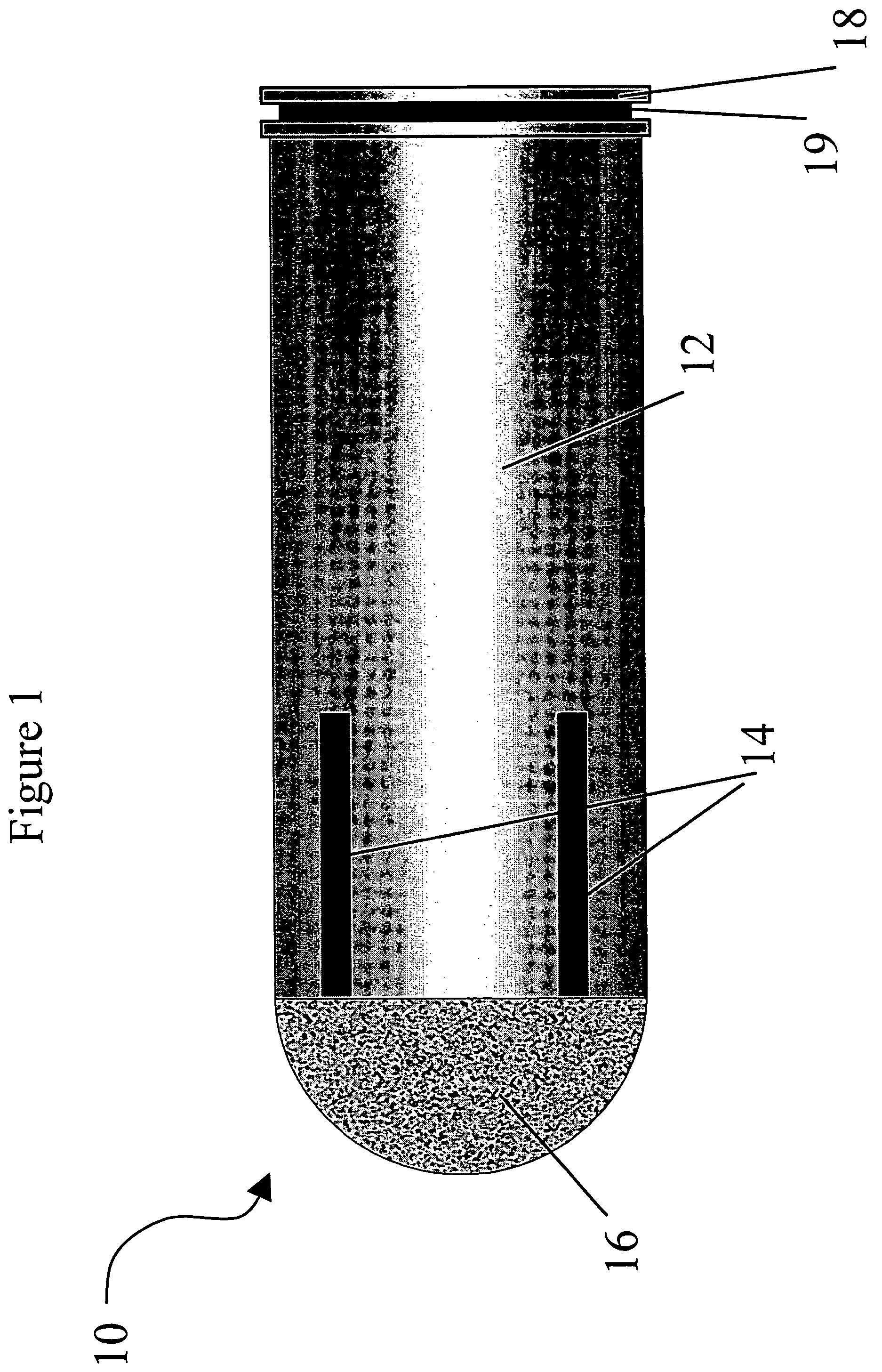
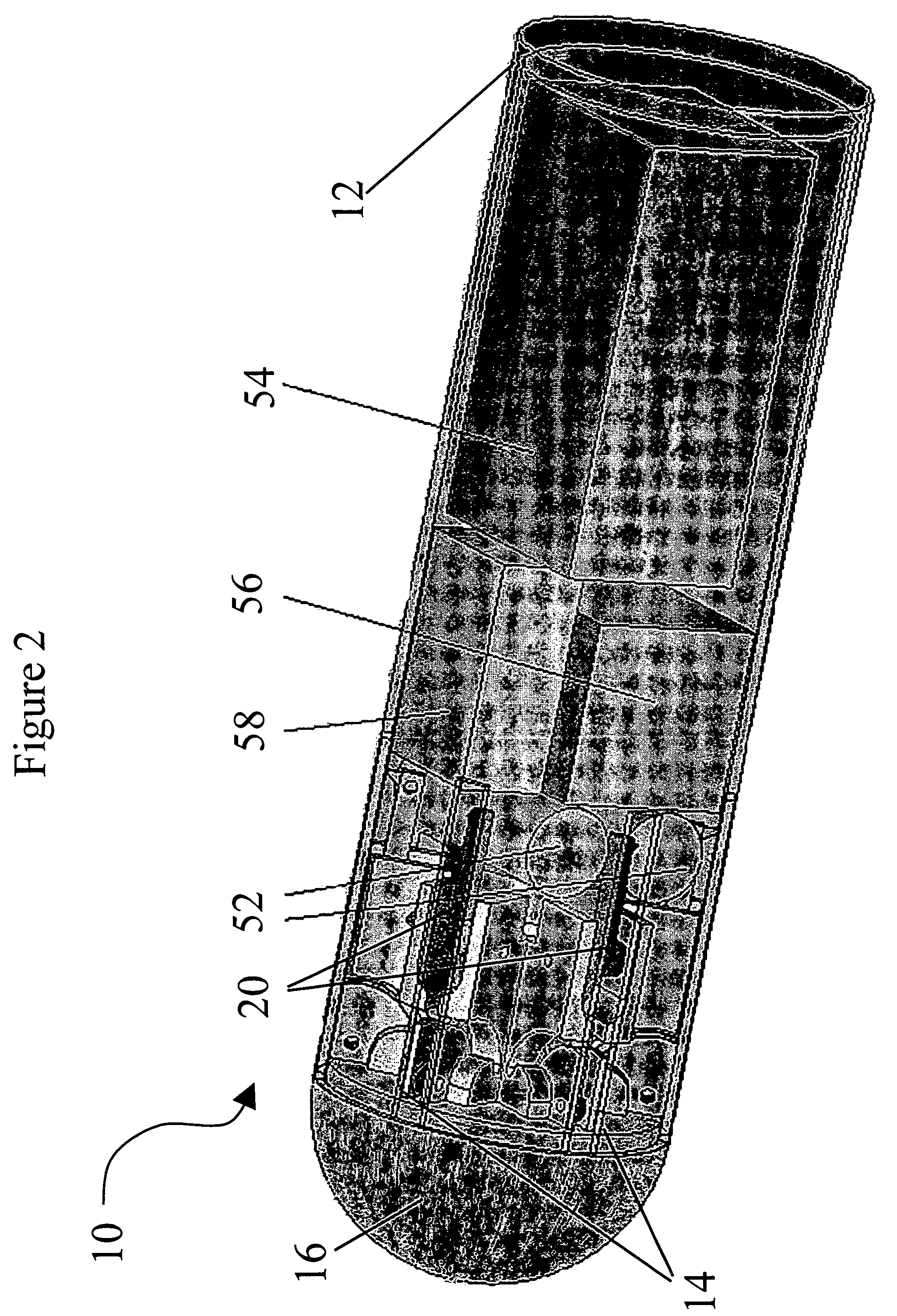
[0079]Projectile 10 may be fired at a range of 10-30 meter without killing. The electrical round is quite heavy. Therefore in order to avoid permanent injury at such short ranges, impact is minimized by an impact reduction subsystem. The impact reduction subsystem acts to: 1) increase the impact area, spreading the impact energy over a wide area and 2) soften the impact by distributing the impact energy over a relatively long time. Increasing the impact area and distributing the impact over time is achieved by means of a deformable pad 16 located on the impact zone of the projectile. In embodiment 10, the preferred ballistic is a flat trajectory as much as possible, (AMAP) in order to achieve, easy aiming and better accuracy. Therefore, the impact is perpendicular and the impact zone is the front of the projectile (marked by deformable pad 16).

[0080]Deformable pad 16 collapses and flattens on impact thus spreading the impact energy on larger area and spreading the impact energy over...
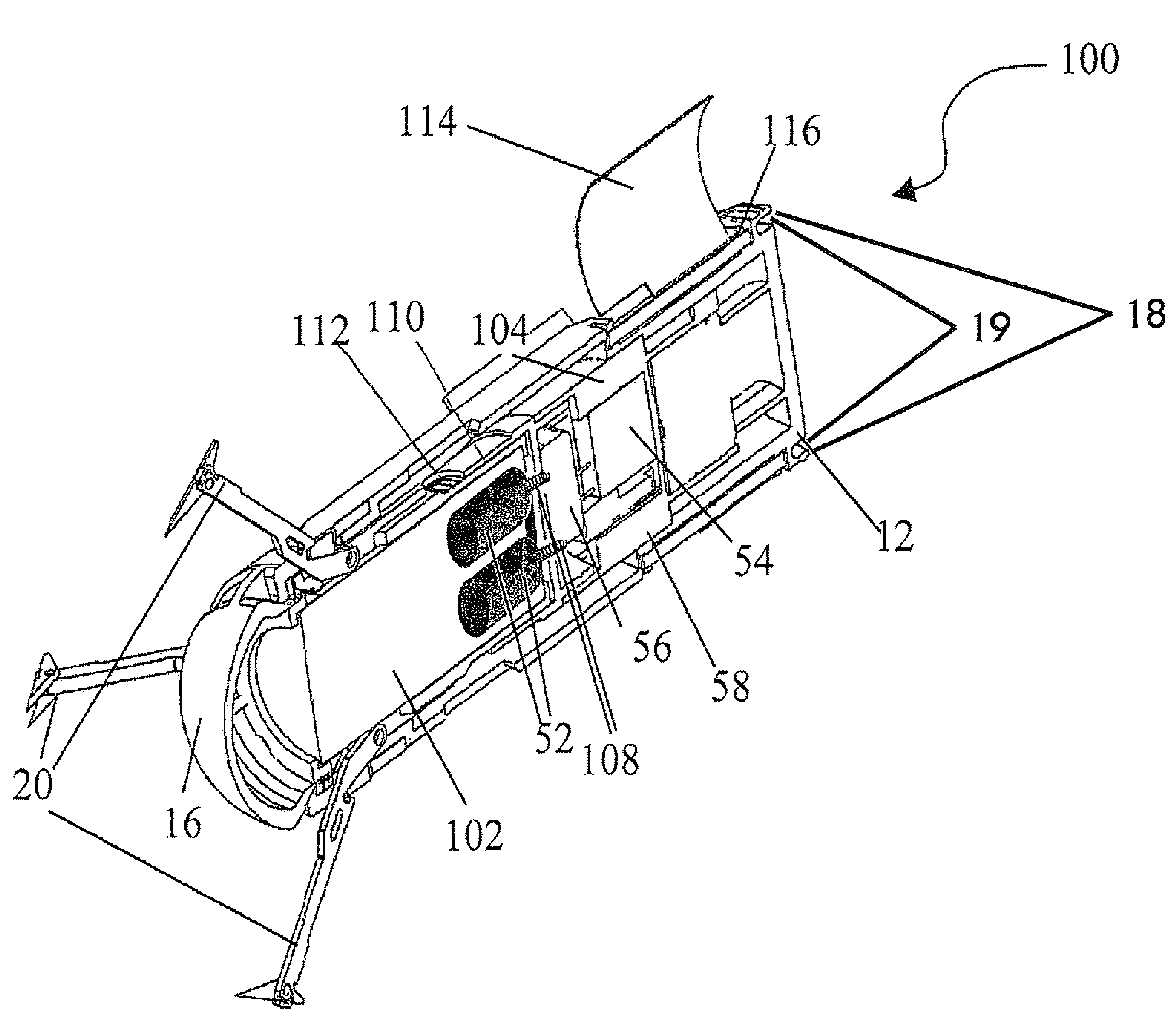
embodiment 100

[0091]Deceleration of mobile subassembly 104 is timed such that the collision between mobile subassembly 104 and rigidly mounted subassembly 102 occurs after the triggering, deployment and extension of spider arms 20 (see FIG. 7). At the moment of collision between mobile subassembly 104 and rigidly mounted subassembly 102, momentum from mobile subassembly 104 is transferred through rigidly mounted subassembly 102 to deployed spider arms 20. This transferred momentum drives spider arms 20 further into the target making it more difficult for the target to untangle himself from the projectile of embodiment 100.

[0092]The stun projectile of embodiment 100 has the following electrical parameters:[0093]output voltage is 50-100 kilovolt (kV)[0094]output current is from 1-10 microampere (μA)[0095]pulse duration is of 10 microsecond-10 millisecond (ms)[0096]repetition rate of 10-40 Hz[0097]working time is from 1 to 5 minute (min).

[0098]Also shown if FIG. 7 is a stability wing 114. Stability ...

embodiment 300

[0101]Upon launch the capsule falls away revealing (FIG. 10) the impact zone of sub-projectile 302a. The impact zone is the exterior of sub-projectile 302a and contains hooks 222, which are designed hold human clothing. Due to elastic properties of high-voltage wire 304, sub-projectiles 302a and 302b move apart to distance limited by the length of high voltage wire 304 (10-50 cm). Each sub-projectile 302a and 302b rotates in space and flies toward target 40. Also upon launch, an inertial switch (not shown) turns on the electrical systems and activates the batteries (not shown) of sub-projectiles 302a and 302b (the electrical system of sub-projectiles 302a and 302b are similar to the electrical system illustrated in FIG. 2). In embodiment 300, battery 52 is contained by sub-projectile 302a and high voltage transformer 54, low voltage transformer 56, and capacitor 58 are all contained in sub-projectile 302b

[0102]FIG. 11 illustrates attachment of the stun projectile of embodiment 300 ...


PUM


Abstract

A projectile launched from a conventional weapon; upon impact with a human target the projectile attaches to the target and stuns and disables the target by applying a pulsed electrical charge. The electric round is defined as non lethal ammunition directed to incapacitate a human, to prevent him from moving for a short time, to prevent him from committing a crime and to allow authorized personnel to arrest the target. A novel thin film technology transformer and thin film technology battery produce an electrical shock capable of stunning a human being in a device the size of a conventional bullet. The transformer and battery are smaller and lighter than conventional transformers and batteries with similar power output.

Description

[0001]This is a continuation-in-part of U.S. Provisional Patent Application No. 60 / 698009, filed Jul. 12, 2005 and U.S. Provisional Patent Application No. 60 / 698010, filed Jul. 12, 2005.FIELD AND BACKGROUND OF THE INVENTION[0002]The present invention relates to a non-lethal wireless stun projectile system, and more specifically to a projectile that is launched from a conventional weapon; upon impact with a human target the system stuns and disables the target by applying a pulsed electrical charge. The electric round is defined as non lethal ammunition directed to incapacitate a human, to prevent him from moving for a short time, to prevent him from committing a crime and to allow authorized personnel to arrest the target.[0003]The electric projectile operates by transmitting electric pulses to the target, paralyzing the target for a short time without clinical after effects. Upon impact the projectile attaches itself to the target and gives the same effect as a regular handle elect...

Claims


Application Information

Patent Timeline
Patent Type & Authority Patents(United States)
IPC IPC(8): F42B12/02F42B30/02
CPCF41H13/0006F42B12/36F42B5/02F41H13/0031A63H5/04F42B12/00
Inventor SHALEV, ILANBEREZNITSKY, MATWEYDANON, HAIMBLAUNSTEIN, NATHANSWARZSHTEIN, GINNADII
Owner SECURITY DEVICES INT INC
Why Eureka
Try Eureka