Workpiece pressing device based on damping and shock absorption

A compression device and damping technology, applied in the direction of the workpiece clamping device, shock absorber, spring/shock absorber, etc., can solve the problems of affecting the machining accuracy of the workpiece, affecting the effect of workpiece compression, and inconvenient compression operation, etc., to achieve Improve stability, facilitate installation and disassembly operations, and facilitate disassembly and installation

Inactive Publication Date: 2019-06-07
李兆林
9 Cites 5 Cited by

AI-Extracted Technical Summary

Problems solved by technology

[0002] During the processing of the current rectangular workpiece, the workpiece needs to be pressed. Generally, a mechanical pressing device is used. During the use of this pressing device, on the one hand, it is easy to shake, which affects the press...

Method used

When the present invention is in use, the workpiece 11 is placed between the first limiting positioning seat 9 and the second limiting positioning seat 10, and the first limiting positioning seat 9 and the second limiting positioning seat 10 can 11 plays a preliminary fixing role to prevent the workpiece 11 from sliding sideways. By driving the rocking bar 16 to move under the action of the drive regulator 14, the triangular rotating plate 18 can be driven to rotate along the stepped rod body 17 under the action of the rocking bar 16, so that the angle of the triangular rotating plate 18 can be adjusted. Under the action of the triangular rotating plate 18, the short connecting rod 21 and the long connecting rod 23 are driven to move, thereby driving the first folded compacting body 25 and the second folded compacting body 29 to move, utilizing the first folded compacting body to move The elastic pressing sheet 33 on the body 25 and the second folded pressing body 29 compresses the w...

Abstract

The invention discloses a workpiece pressing device based on damping and shock absorption. The device comprises a bottom mounting plate body, an upper supporting plate body, a plurality of damping shock absorbers, a first rectangular supporting rod, a second rectangular supporting rod, a first supporting plate body, a second supporting plate body, a positioning plate body, a first limiting positioning seat, a second limiting positioning seat, a lug supporting seat, a driving adjuster, a rocker, a stepped rod body, a triangular rotating plate, a short connecting rod, a long connecting rod, a first folding pressing body, a first groove type piece, a second folding pressing body and a second groove type piece, wherein elastic pressing pieces are installed on the pressing end face of the firstfolding pressing body and the pressing end face of the second folding pressing body through fasteners. The device is reasonable in overall structural design, and convenient to mount, dismount and use.

Application Domain

Technology Topic

Image

  • Workpiece pressing device based on damping and shock absorption
  • Workpiece pressing device based on damping and shock absorption
  • Workpiece pressing device based on damping and shock absorption

Examples

  • Experimental program(1)

Example Embodiment

[0015] In order to make the objectives, technical solutions and advantages of the present invention clearer, the following further describes the present invention in detail with reference to the accompanying drawings and embodiments. It should be understood that the specific embodiments described herein are only used to explain the present invention, but not to limit the present invention.
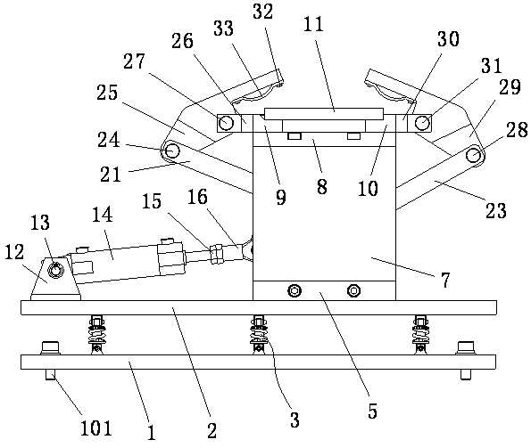
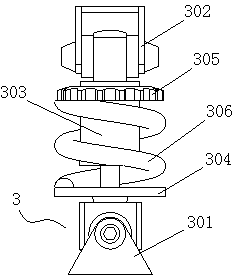
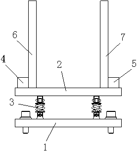
[0016] Such as Figure 1-Figure 5 As shown, the workpiece pressing device based on damping and shock absorption includes a bottom mounting plate body 1, an upper supporting plate body 2 located above the bottom mounting plate body 1 and arranged parallel to the bottom mounting plate body 1 A plurality of damping shock absorbers 3 are installed between the bottom mounting plate body 1 and the upper support plate body 2; a first rectangular support rod 4 is installed on the upper end side of the upper support plate body 2 through bolts, A second rectangular support rod 5 is installed on the other side of the upper end of the upper support plate body 2 through bolts, and a first support plate body 6 is installed at one end of the first rectangular support rod 4 through bolts. A second support plate body 7 is installed at one end of the support rod 5 by bolts, a positioning plate body 8 is installed on the top of the first support plate body 6 and the second support plate body 7, and a positioning plate body 8 is installed on the upper end of the positioning plate body 8. A first limiting positioning seat 9 is installed on one side, and a second limiting positioning seat 10 is installed on the other side of the upper end of the positioning plate body 8. The workpiece 11 is placed on the first limiting positioning seat 9 and the second limiting positioning seat 9 Between the two limit positioning seats 10; an ear support seat 12 is installed on the upper end of the upper support plate body 2, and a drive adjuster 14 is installed on the ear support seat 12 through a pin 13. The drive The drive rod of the adjuster 14 is connected to the rocker 16 through a coupling 15; a stepped rod body 17 is installed on the first supporting plate body 6, and one end of the stepped rod body 17 is mounted on the triangular rotating plate 18 through a bearing The rocker 16 is mounted on the triangular rotating plate 18 through a first movable shaft 19, and a short connecting rod 21 is movably mounted on one end of the triangular rotating plate 18 through a second movable shaft 20. The other end of the rotating plate 18 is movably installed with a long connecting rod 23 through the third movable shaft 22; one end of the short connecting rod 21 is connected to the first folding pressing body 25 through the first connecting shaft 24, and is connected to the first One end of a limit positioning seat 9 is installed with a first groove-shaped member 26 through a bolt, and the first groove-shaped member 26 is connected to the first folding pressing body 25 through a second connecting shaft 27; One end of the rod 23 is connected to the second folding pressing body 29 through the third connecting shaft 28, and a second groove-shaped member 30 is installed at one end of the second limit positioning seat 10 through a bolt, and the second groove The shaped member 30 is connected to the second folding pressing body 29 through the fourth connecting shaft 31; the pressing end faces of the first folding pressing body 25 and the second folding pressing body 29 are both passed through The firmware 32 is equipped with an elastic pressing piece 33.
[0017] The elastic compression piece 33 includes a first strip-shaped installation section, an arc-shaped protrusion compression section, and a second strip-shaped installation section. The first strip-shaped installation section and the second strip-shaped installation section pass through fasteners 32. Install on the pressing end surface.
[0018] The drive regulator 14 is a single-rod double-acting hydraulic cylinder.
[0019] A plurality of fixing members 101 are installed on the bottom mounting board body 1, so that the bottom mounting board body 1 is fixedly installed.
[0020] Four U-shaped grooves 801 are processed on the positioning plate body 8, and bolts are installed in each U-shaped groove 801, so that the positioning plate body 8 is installed on the first support plate body 6 and the second support plate On the top of the body 7, the first limit positioning seat 9 and the second limit positioning seat 10 are all mounted on the positioning plate body 8 by bolts.
[0021] The damping shock absorber 3 includes a bottom seat body 301 installed at the upper end of the bottom mounting plate body 1, a top seat body 302 installed at the lower end of the upper support plate body 2, and the bottom seat body 301 and the top seat body 302 A damping telescopic member 303 is installed between the bodies 302, a spring bottom limit support plate 304 is arranged above the bottom seat body 301, and a spring top limit adjustment plate 305 is arranged below the top seat body 302, and A shock-absorbing spring 306 is installed between the spring bottom limit support plate 304 and the spring top limit adjustment plate 305.
[0022] When the present invention is in use, the workpiece 11 is placed between the first limit positioning seat 9 and the second limit positioning seat 10, and the first limit positioning seat 9 and the second limit positioning seat 10 can affect the workpiece 11 The preliminary fixing effect prevents the workpiece 11 from sliding sideways. By driving the rocker 16 to move under the action of the drive adjuster 14, the triangular rotating plate 18 can be driven to rotate along the stepped rod body 17 under the action of the rocker 16, so that the angle of the triangular rotating plate 18 can be adjusted. Under the action of the triangular rotating plate 18, the short connecting rod 21 and the long connecting rod 23 are driven to move, thereby driving the first folding pressing body 25 and the second folding pressing body 29 to move, and the first folding pressing The elastic pressing piece 33 on the body 25 and the second fold-shaped pressing body 29 compresses the workpiece 11, thereby preventing the workpiece 11 from moving. When the driving rod of the driving adjuster 14 extends, what is executed is The pressing action on the work piece 11, when the drive rod of the drive adjuster 14 is retracted, is performed to loosen the work piece 11. The elastic pressing piece 33 in the present invention adopts an arc-shaped convex pressing structure, which can well compress the workpiece 11, and the elastic pressing piece 33 is easy to disassemble and install, thereby facilitating replacement. By installing a plurality of damping shock absorbers 3 between the bottom mounting plate 1 and the upper supporting plate 2, it can play the role of damping and prevent the workpiece 11 from shaking during the compaction process, thereby improving compaction The stable performance of the device. The overall structure of the invention is reasonable in design, convenient for installation and disassembly operations, and convenient for use.
[0023] The above are only the preferred embodiments of the present invention and are not intended to limit the present invention. Any modification, equivalent replacement and improvement made within the spirit and principle of the present invention shall be included in the protection of the present invention. Within range.

PUM

no PUM

Description & Claims & Application Information

We can also present the details of the Description, Claims and Application information to help users get a comprehensive understanding of the technical details of the patent, such as background art, summary of invention, brief description of drawings, description of embodiments, and other original content. On the other hand, users can also determine the specific scope of protection of the technology through the list of claims; as well as understand the changes in the life cycle of the technology with the presentation of the patent timeline. Login to view more.

Similar technology patents

Classification and recommendation of technical efficacy words

  • Easy to replace
  • Easy to install and remove

Dielectric barrier discharge lamp

InactiveUS20100244688A1Easy to replaceSolid cathode detailsGas discharge lamp detailsDielectric barrier dischargeEngineering
Owner:SIGNIFY HLDG BV

Moment frame links wall

ActiveUS20050257451A1Increase initial stiffnessEasy to replaceHuman health protectionWallsEngineeringSupporting system
Owner:SIMPSON STRONG TIE

Automated tightening shoe

ActiveUS8904672B1Easy to looseEasy to replaceFasteningsUpperEngineeringShoe laces
Owner:HANDS FREE ENTERPRISES LLC
Why Eureka
Try Eureka