Hub orienting and light-emitting vehicle logo

A car logo and wheel hub technology, which is applied in the field of auto parts, can solve the problems that the car logo cannot be seen clearly at night, the directional car logo cannot be illuminated, and the illuminated car logo cannot see the shape of the car logo. Reliable effect

Pending Publication Date: 2019-06-07
GUANGZHOU JINZHONG AUTO PARTS MFG
6 Cites 9 Cited by

AI-Extracted Technical Summary

Problems solved by technology

However, the directional car logo cannot be illuminated, and there is a defect that it cannot be seen clearly at n...

Method used

As shown in Figure 1, a kind of wheel hub directional light-emitting car mark, mounting plate 4, counterweight 5, be located at the lamp bead plate 3 on the mounting plate 4, cover the decorative cover 2 on the lamp bead plate 3, The base 7 , the protective cover 1 matched with the base 7 and the outer rotor generator 6 that supplies power to the lamp bead board 3 . The protective cover 1 cooperates with the base 7 to form an accommodating cavity, and the decorative cover 2, counterweight 5, lamp bead board 3, mounting plate 4 and outer rotor generator 6 are arranged in the accommodating cavity. The protective cover 1 is a transparent part, and the joint between the protective cover 1 and the base 7 is provided with a sealing ring, so as to ensure that the parts in the accommodating cavity will not be affected by the external environment and prolong its service life.
Principle of the present invention: the rotor 63 of generator 6 is connected with base 7, and base 7 is connected with hub, and hub rotates and drives base 7 and rotor 63; Counterweight 5 is connected with mounting plate 4, and stator 62 is connected with mounting plate 4 , in a static state, the counterweight 5 is at the lower end of the mounting plate 4 under the action of gravity, and the LOGO on the decorative cover 2 is in the correct direction; when the rotor 63 rotates with the hub, the rotor 63 produces a certain pulling force on the stator 62, but in Under the action of the counterweight 5, the stator 62 is still unable to rotate, so as to maintain a static position, that is, realize the function of orienting the car logo; the rotor 63 rotates relative to the stator 62 to generate electric energy, and this part of electric energy is directly supplied to the lamp bead board 3 to emit light, and the light The shape of the vehicle logo can be presented through the light-transmitting decorative cover 2, especially at night. Both the generator 6 and the counterweight 5 of the present invention are installed by bolts, the installation is simple and convenient, and the reliability is high.
[0020] As shown in Figure 1, the axial core 61 of the stator 62 is connected to the mounting plate 4, the counterweight 5 is located on the edge of the mounting plate 4 and the counterweight 5 is connected to the mounting plate 4 by bolts. The mounting plate 4 and the stator 62 will not rotate under the action of the counterweight 5 . In addition, the counterweight and the mounting plate can be formed by integral die-casting, which further reduces parts and simpli...

Abstract

The invention provides a hub orienting and light-emitting vehicle logo. The hub orienting and light-emitting vehicle logo comprises a mounting plate, a balancing weight, a lamp bead plate arranged onthe mounting plate, a decoration cover covering the lamp bead plate, a base, a protecting cover matched with the base and an outer rotor power generator for supplying power to the lamp bead plate; theprotecting cover and the base are matched to form an accommodating cavity, and the decoration cover, the balancing weight, the lamp bead plate, the mounting plate and the outer rotor power generatorare arranged in the accommodating cavity; mounting holes are formed in the middle area of the bottom of the base, a plurality of clamping feet are arranged at the edge of the bottom of the base, the outer rotor power generator comprises a rotor and a stator arranged in the rotor, and the rotor is fixed to the bottom of the base through bolts; and a shaft core of the stator is connected with the mounting plate, and the balancing weight is arranged at the edge of the mounting plate and connected with the mounting plate through a bolt. The outer rotor power generator, the lamp bead plate and thebalancing weight are organically combined, and thus the hub orienting and light-emitting vehicle logo has the orienting function and the light-emitting function.

Application Domain

Wheel protectionIlluminated signs

Technology Topic

StatorEngineering +1

Image

  • Hub orienting and light-emitting vehicle logo
  • Hub orienting and light-emitting vehicle logo

Examples

  • Experimental program(1)

Example Embodiment

[0016] The present invention will be further explained below in conjunction with the accompanying drawings of the specification.
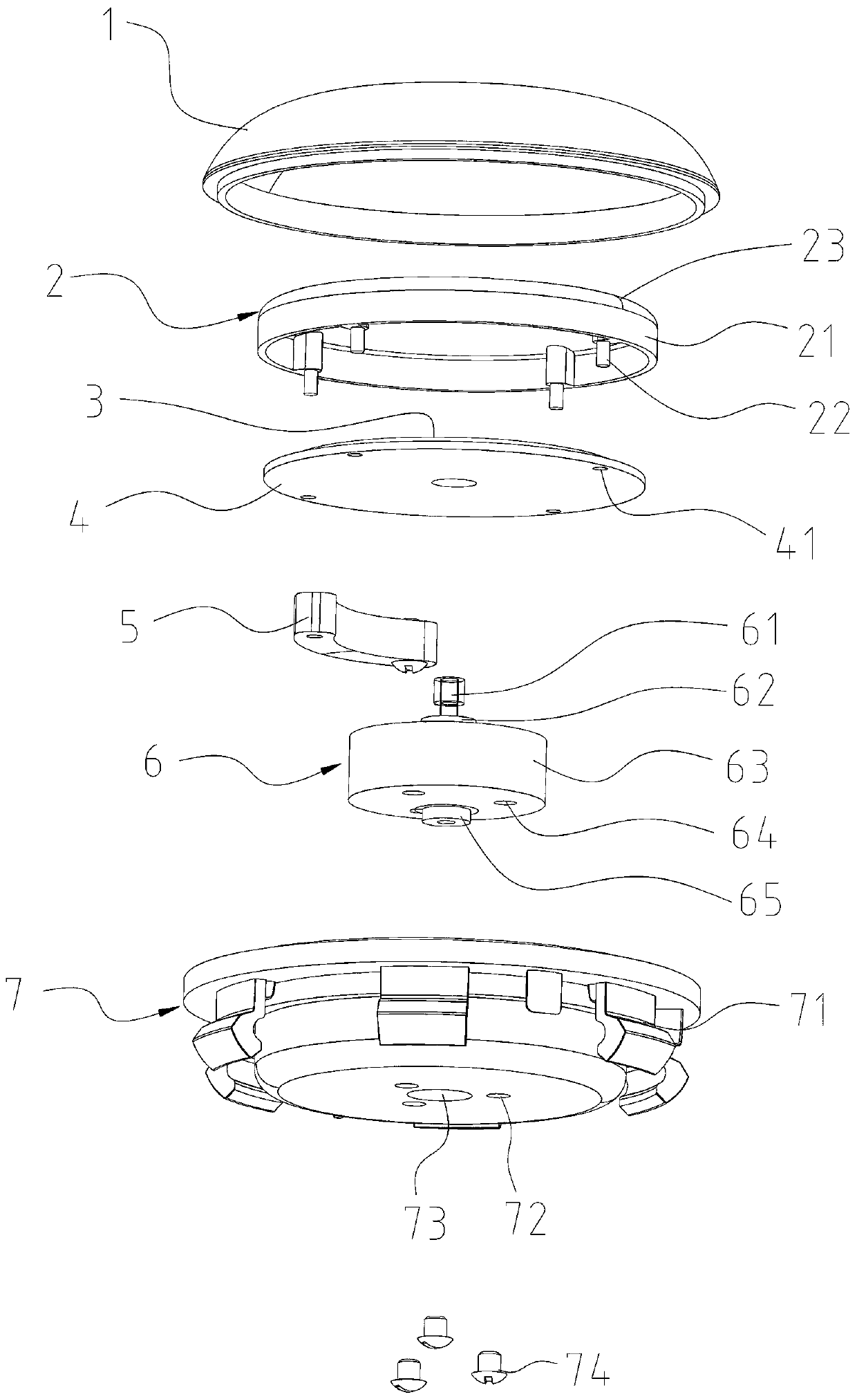
[0017] Such as figure 1 As shown, a wheel directional luminous vehicle logo, a mounting plate 4, a counterweight 5, a lamp bead plate 3 arranged on the mounting plate 4, a decorative cover 2, a base 7, and a base 7 covered on the lamp bead plate 3 The matched protective cover 1 and the outer rotor generator 6 supplying power to the lamp bead plate 3. The protective cover 1 cooperates with the base 7 to form an accommodating cavity, and the decorative cover 2, the counterweight 5, the lamp bead plate 3, the mounting plate 4 and the outer rotor generator 6 are arranged in the accommodating cavity. The protective cover 1 is a transparent piece, and a sealing ring is arranged at the junction of the protective cover 1 and the base 7 to ensure that the parts in the accommodating cavity will not be affected by the external environment and prolong its service life.
[0018] Such as figure 1 As shown, the bottom edge of the base 7 is provided with a number of clamping feet 71 which are directly connected with the hub, and the base 7 rotates with the hub. A shaft hole 73 is provided in the middle of the bottom of the base 7, and three mounting holes 72 are provided around the shaft hole 73 for installing the generator 6.
[0019] Such as figure 1 As shown, the outer rotor generator 6 includes a rotor 63 and a stator 62 arranged in the rotor 63. The rotor 63 includes a housing and a magnetic tile set in the housing. The housing includes a bottom plate and a surrounding plate around the edge of the bottom plate. A bearing 65 is provided at the middle of the outer side of the bottom plate, and one end of the shaft core 61 of the stator 62 is provided. In the bearing 65, the bearing 65 is provided in the shaft hole 73. The bottom plate of the shell is provided with three screw holes 64. When installed, the shell is attached to the bottom of the base 7 and the shell is fixed on the bottom of the base 7 by bolts 74. The rotor 63 rotates with the base 7 and the hub. The rotor shell and the base can also be integrated by injection molding, which reduces the assembly process and improves the reliability of the generator installation.
[0020] Such as figure 1 As shown, the shaft core 61 of the stator 62 is connected to the mounting plate 4, the counterweight 5 is provided on the edge of the mounting plate 4, and the counterweight 5 is connected to the mounting plate 4 by bolts. The mounting plate 4 and the stator 62 will not rotate under the action of the counterweight 5. In addition, the counterweight and the mounting plate can be formed by integral die-casting, further reducing parts and simplifying the assembly process.
[0021] Such as figure 2 As shown, the decorative cover 2 includes a transparent injection molded body 21 and a decorative sheet 23, and the back of the decorative sheet 23 is attached to the front of the molded body 21. The front surface of the injection molding body 21 is curved and convex, which makes the vehicle logo have a three-dimensional effect. The back of the injection molding body 21 is provided with a clip 22 for fixing with the wheel hub. The decorative sheet 23 includes a plastic sheet, and the back of the plastic sheet is provided with a shielding area 232 and a light transmitting area 231; the shielding area 232 is covered with a black coating, and the black coating cannot transmit light; the light transmitting area 231 The electroplating layer is formed by vacuum electroplating, and light can penetrate the electroplating layer. The light-transmitting area 231 of this embodiment includes an outer ring 2312 arranged on the edge of the plastic sheet, and an inner circle arranged in the middle of the plastic sheet The ring 2313 and the pattern 2311 provided in the inner ring 2313, except for the above-mentioned three light-transmitting areas 231, are all shielding areas 232. The light-transmitting area 231 of this form has a sense of hierarchy and is more aesthetic. The injection molding body 21 and the decorative sheet 23 are bonded together by in-mold injection molding, the two are firmly combined, and the decorative sheet 23 is not easy to fall off. The edge of the decorative cover 2 is provided with a peripheral edge, which can play a role of shading and prevent light from the side; the mounting plate 4 is provided with a limiting hole 41 corresponding to the clip 22, and the decorative cover is fixed by the clip 22 The decorative cover 2 can also be directly fixed on the mounting plate 4 by glue, which has good adhesion and sealing. In the decorative cover, light can pass through the transparent injection-molded body 21. Because of the black coating, the light cannot penetrate, and the electroplated layer of the light-transmitting area 231 can emit light, so the entire decorative cover can be transparent at night The shape of the area, the transparent area is designed as a car logo to achieve the display effect. The invention has simple structure, simple manufacturing process, and obvious vehicle logo LOGO display effect.
[0022] The principle of the invention: the rotor 63 of the generator 6 is connected to the base 7, the base 7 is connected to the hub, the hub rotates to drive the base 7 and the rotor 63; the counterweight 5 is connected to the mounting plate 4, and the stator 62 is connected to the mounting plate 4 in a static state Under the action of gravity, the counterweight 5 is at the lower end of the mounting plate 4, and the LOGO on the decorative cover 2 is in the correct direction; when the rotor 63 rotates with the hub, the rotor 63 generates a certain pulling force on the stator 62, but the counterweight Under the action of 5, the stator 62 still cannot rotate, so as to maintain the static position, which realizes the function of directional vehicle logo; the rotor 63 rotates relative to the stator 62 to generate electric energy, which is directly supplied to the lamp bead plate 3 to emit light, and the light is transparent The light decorative cover 2 can show the shape of the car logo, especially at night. The generator 6 and the counterweight 5 of the present invention are both installed by bolts, the installation is simple and convenient, and the reliability is high.

PUM

no PUM

Description & Claims & Application Information

We can also present the details of the Description, Claims and Application information to help users get a comprehensive understanding of the technical details of the patent, such as background art, summary of invention, brief description of drawings, description of embodiments, and other original content. On the other hand, users can also determine the specific scope of protection of the technology through the list of claims; as well as understand the changes in the life cycle of the technology with the presentation of the patent timeline. Login to view more.

Similar technology patents

Scraper pan positioning device and method for backhoe excavator

ActiveCN103852059AEasy to installgood measurement
Owner:CHINESE NONFERROUS METAL SURVEY & DESIGN INSTITUE OF CHANGSHA

Fence and installation method thereof

Owner:ZHANGJIAGANG GOLDNET FENCING SYST

Classification and recommendation of technical efficacy words

  • Improve reliability
  • Easy to install

Organic light emitting diode display

ActiveUS20070008268A1improve reliability
Owner:LG DISPLAY CO LTD

Method and apparatus for correcting errors in memory device

ActiveUS20120151294A1improve reliability
Owner:SAMSUNG ELECTRONICS CO LTD

Multiple branch predictions

ActiveUS20050268075A1improve reliabilityfacilitate availability
Owner:ORACLE INT CORP

Cooking electric appliance

PendingCN107647763AEasy to installAvoid insulation loss
Owner:FOSHAN SHUNDE MIDEA ELECTRICAL HEATING APPLIANCES MFG CO LTD

System for monitoring vibration of rotating machinery rolling bearing in wireless mode

InactiveCN102053016Ameasurementanalysisdatareal-timeEasy to install
Owner:JIANGSU UNIV
Why Eureka
Try Eureka