AI technical title is built by Patsnap AI team. It summarizes the technical point description of the patent document.
A vehicle power and control system technology, applied in the field of vehicle power control systems, can solve the problems of inability to monitor and control tires, and inability to monitor and control each tire.
Inactive Publication Date: 2019-06-07
SHENZHEN DAKEQI TECH CO LTD
View PDF0 Cites 2 Cited by
Summary
Abstract
Description
Claims
Application Information
AI Technical Summary
This helps you quickly interpret patents by identifying the three key elements:
Problems solved by technology
Method used
Benefits of technology
Problems solved by technology
[0002] The control of the direction of the existing vehicle is limited to the direction control of the front wheels; and the speed control of the vehicle is limited to the speed control of the overall vehicle; it is not possible to closely monitor and control each tire of the vehicle. It can accurately monitor and control each tire of the vehicle body. In the rapidly developing modern age, intelligent and automated vehicles will become our new means of transportation. Therefore, it is necessary to monitor and control each tire of the vehicle in order to achieve intelligence. Automated Safe Driving
Method used
Image
Click on the blue label to locate the original text in one second.
Reading with bidirectional positioning of images and text.
Examples
no. 1 example
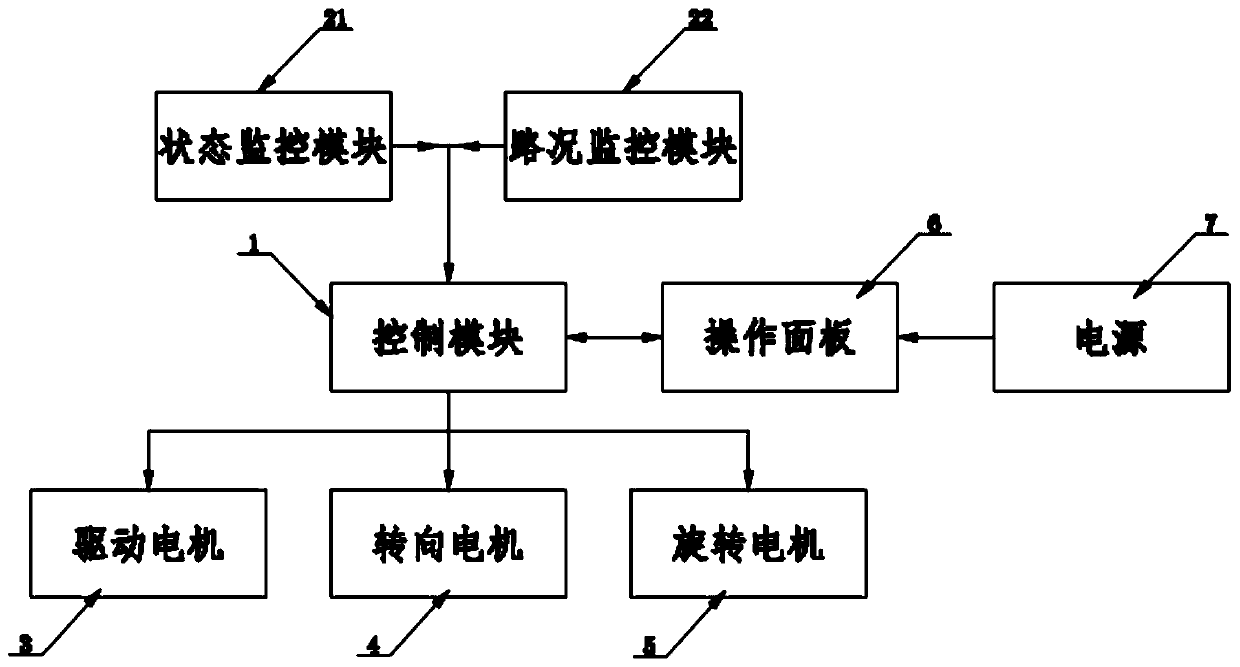
[0027] combine Figure 1 , Figure II As shown, a vehicle power control system includes: a control module 1, a monitoring module 2, a drive motor 3, a steering motor 4, and a rotating motor 5; the monitoring module 1 is electrically connected to the control module 2; the control module 2 is electrically connected Connected to drive motor 3, steering motor 4, and rotating motor 5.
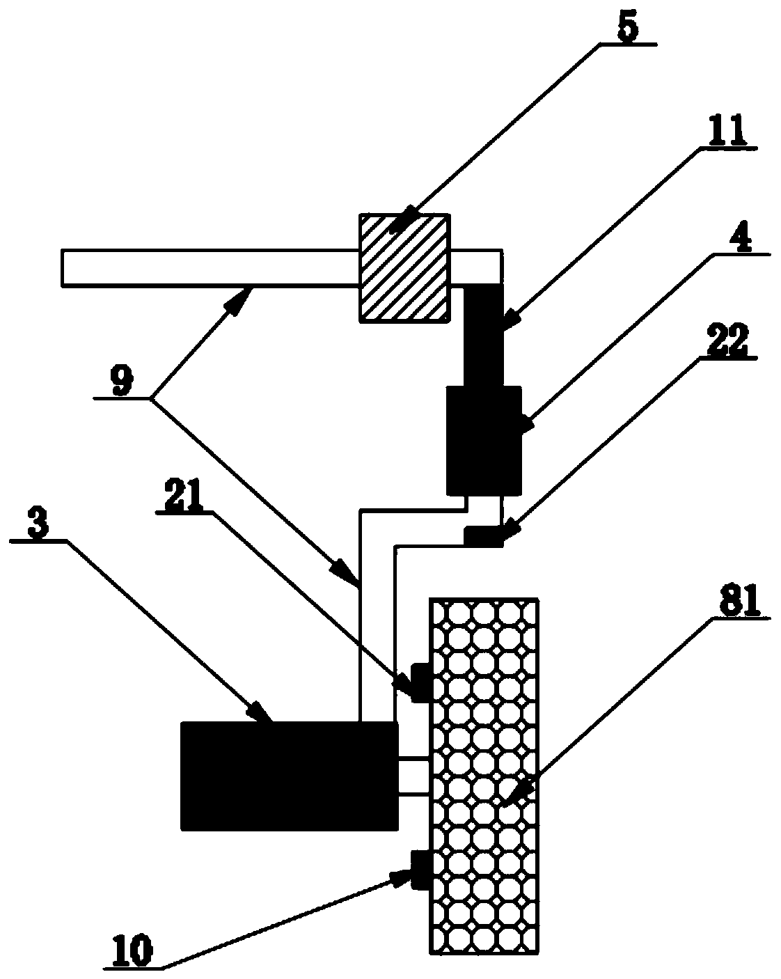
[0028] Preferably, the monitoring module 2 includes a state monitoring module 21 and a road condition monitoring module 22; the state monitoring module 21 is arranged inside the tire 81; .
[0029] Preferably, it also includes: an electric brake pad 10, an operation panel 6, a power supply 7, a telescopic arm 11, and a vehicle frame 9; the power supply 7 is electrically connected to the operation panel 6, and the operation panel 6 is electrically connected to the control module 1, so The control module 1 is electrically connected to the electric brake pad 10 , the telescopic arm 11 , and the stat...
no. 2 example
[0046] The difference between the second embodiment and the first embodiment is: the state monitoring module 21 is a combination of a real-time rotational speed sensor and a real-time direction sensor;
[0047] The road condition monitoring module is set as a video monitor;
[0048] The telescopic arm 11 is an electric telescopic arm.
[0049] A vehicle power control method, comprising the following steps:
[0050] S1: transmit the monitoring information to the control module 1 through the monitoring module 2, and display the monitoring information on the operation panel 6 for users to see;
[0051] S2: According to the information displayed on the operation panel 6, the user or the intelligent automation system selects the interface corresponding to the operation panel 6, and sends instructions to the control module 1 through the operation panel 6;
[0052] S3: The control module 1 controls the rotation of the driving motor 3, the steering motor 4, the rotating motor 5 and ...
PUM
Abstract
The invention discloses a vehicle power controlsystem and method. The vehicle power controlsystem comprises a control module, a monitoring module, a driving motor, a steering motor and a rotating motor. The monitoring module is electrically connected to the control module. The control module is electrically connected to the driving motor, the steering motor and the rotating motor. The vehicle power controlsystem effectively monitors the power system of the vehicle, and transmits the monitoring information to an operation panel, a user or an intelligent automation system can give corresponding commands according to the state information and the road condition information of each tire, the direction and speed of each tire are accurately controlled, and the intelligent automatic safe driving is achieved.
Description
technical field [0001] The invention relates to the technical field of tires, in particular to a vehicle power control system and method. Background technique [0002] The control of the direction of the existing vehicle is limited to the direction control of the front wheels; and the speed control of the vehicle is limited to the speed control of the overall vehicle; it is not possible to closely monitor and control each tire of the vehicle. It can accurately monitor and control each tire of the vehicle body. In the rapidly developing modern age, intelligent and automated vehicles will become our new means of transportation. Therefore, it is necessary to monitor and finely control each tire of the vehicle to achieve intelligence. Automate safe driving. Contents of the invention [0003] The present invention achieves the above object through the following technical solutions: [0004] A vehicle power control system, comprising: a control module, a monitoring module, a d...
Claims
Application Information
Patent Timeline
Application Date:The date an application was filed.
Publication Date:The date a patent or application was officially published.
First Publication Date:The earliest publication date of a patent with the same application number.
Issue Date:Publication date of the patent grant document.
PCT Entry Date:The Entry date of PCT National Phase.
Estimated Expiry Date:The statutory expiry date of a patent right according to the Patent Law, and it is the longest term of protection that the patent right can achieve without the termination of the patent right due to other reasons(Term extension factor has been taken into account ).
Invalid Date:Actual expiry date is based on effective date or publication date of legal transaction data of invalid patent.

