
LED lens and LED lamp containing the same

A LED lens and transparent technology, which is applied to the parts of lighting devices, semiconductor devices of light-emitting elements, lighting devices, etc., can solve the problems of inability to use LED side light energy, low uniformity of illuminance on the illuminated surface, and low energy utilization rate, etc. problem, to achieve the effect of improving light utilization rate, high light utilization rate and uniform light output

Active Publication Date: 2016-04-13
OCEANS KING LIGHTING SCI&TECH CO LTD +1
View PDF4 Cites 0 Cited by
  • Summary
  • Abstract
  • Description
  • Claims
  • Application Information

AI Technical Summary

Problems solved by technology

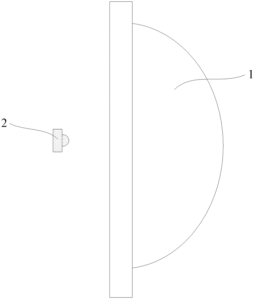
However, this secondary light distribution lens in the form of a concave-convex mirror cannot use the light energy on the side of the LED, so the energy utilization rate is low, usually below 80%. , so that the illumination uniformity of the illuminated surface is not high

Method used


Image

  • LED lens and LED lamp containing the same
  • LED lens and LED lamp containing the same
  • LED lens and LED lamp containing the same

Examples


Embodiment Construction

[0034] In order to facilitate the understanding of the present invention, the present invention will be described more fully below with reference to the associated drawings. Preferred embodiments of the invention are shown in the accompanying drawings. However, the present invention can be embodied in many different forms and is not limited to the embodiments described herein. On the contrary, these embodiments are provided to make the understanding of the disclosure of the present invention more thorough and comprehensive.

[0035] It should be noted that when an element is referred to as being “fixed” to another element, it can be directly on the other element or there can also be an intervening element. When an element is referred to as being "connected to" another element, it can be directly connected to the other element or intervening elements may also be present. The terms "vertical," "horizontal," "left," "right," and similar expressions are used herein for purposes ...


PUM


Abstract

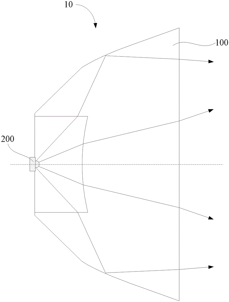
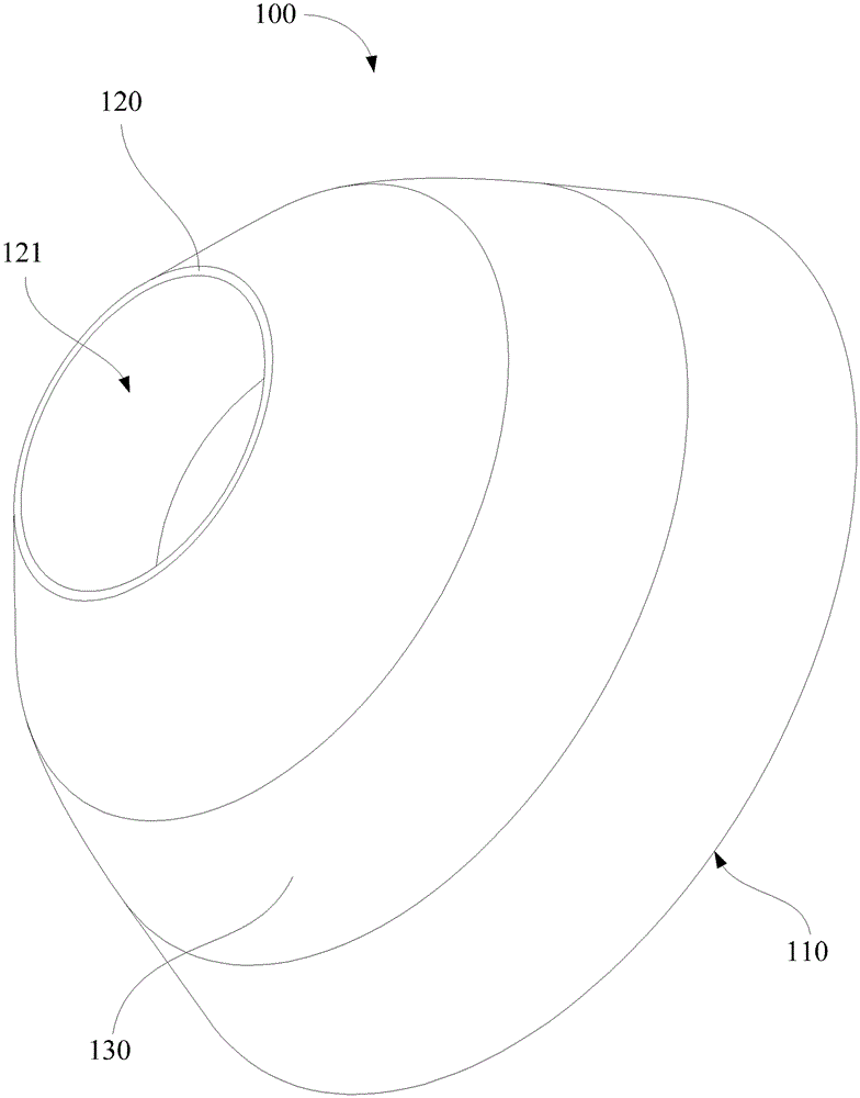
A light emitting diode (LED) lens comprises a lens body which is provided with a top surface, a bottom surface and a curve lateral surface, wherein the bottom surface is arranged opposite to the top surface. A groove is formed in the bottom surface of the transparent lens body. The groove is symmetrical with an optical axis of the LED lens as a symmetry axis in a rotating mode. A bottom wall, opposite to the top surface, of the groove is a free-form surface and protrudes towards an opening of the groove. The curve lateral surface is connected with the top surface and the bottom surface. The curve lateral surface is a free-form surface with the optical axis of the LED lens as a rotating symmetry axis and protrudes back on to the LED lens. The lateral wall and the bottom wall of the groove are light inlet surfaces and the top wall of the groove is a light outlet surface. Due to the fact that the curve lateral surface of the LED lens and the bottom wall of the groove are both free-form surfaces in shape, a secondary grading structure is formed; due to the fact that the free-form surfaces are capable of accurately controlling the direction of light, even light spots are formed; and due to the fact that light emitted from the lateral surface of the LED lens is refracted out from the top surface after being reflected through the curve lateral surface, utilization rate of the light is improved. The invention further provides an LED lamp.

Description

【Technical field】 [0001] The invention relates to a lens, in particular to an LED lens and an LED lamp containing the LED lens. 【Background technique】 [0002] With the continuous improvement of LED (Light Emitting Diode) technology, the luminous efficiency and luminous flux of a single LED continue to increase. Followed by a single LED as the light source of the lighting system will continue to increase. However, the light emitted from the surface of LED chips has a Lambertian distribution, which cannot be directly applied to lighting systems. Therefore, the design of the secondary light distribution lens with LED as the light source is particularly important. [0003] At present, the lenses that can achieve uniform light distribution on the market are mainly based on figure 1 Appears in the form of , where 2 means LED point light source, and 1 means secondary light distribution lens. Generally, the secondary light distribution lens adopts at least one aspherical surfac...

Claims


Application Information

Patent Timeline
Patent Type & Authority Patents(China)
IPC IPC(8): F21V5/04F21V19/00F21Y115/10
Inventor 周明杰杜金
Owner OCEANS KING LIGHTING SCI&TECH CO LTD
Learn More