
Non-engaged-transmission steel wire winding robot

A technology of steel wire winding and robotics, applied in manipulators, manufacturing tools, etc., can solve problems such as large deformation, failure to meet quality standards, affect project progress and winding quality, and achieve the effect of improving walking reliability and solving transmission problems

Pending Publication Date: 2019-06-07
KUNSHAN YONGNIAN ADVANCED MFG TECH
View PDF0 Cites 0 Cited by
  • Summary
  • Abstract
  • Description
  • Claims
  • Application Information

AI Technical Summary

Problems solved by technology

However, the rack or chain used for transmission will not change accordingly, so that the fixing screws of the fixed rack or chain will be cut off or the fixed solder joints will be broken continuously.
However, due to the large amount of deformation, the super-large workpiece (tens of meters) often needs to be stopped for reinforcement, which seriously affects the progress of the project and the quality of the winding, and cannot meet the ideal quality standard.

Method used


Image

  • Non-engaged-transmission steel wire winding robot
  • Non-engaged-transmission steel wire winding robot
  • Non-engaged-transmission steel wire winding robot

Examples


Embodiment

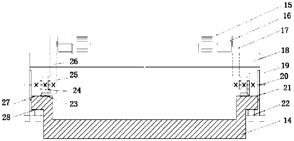
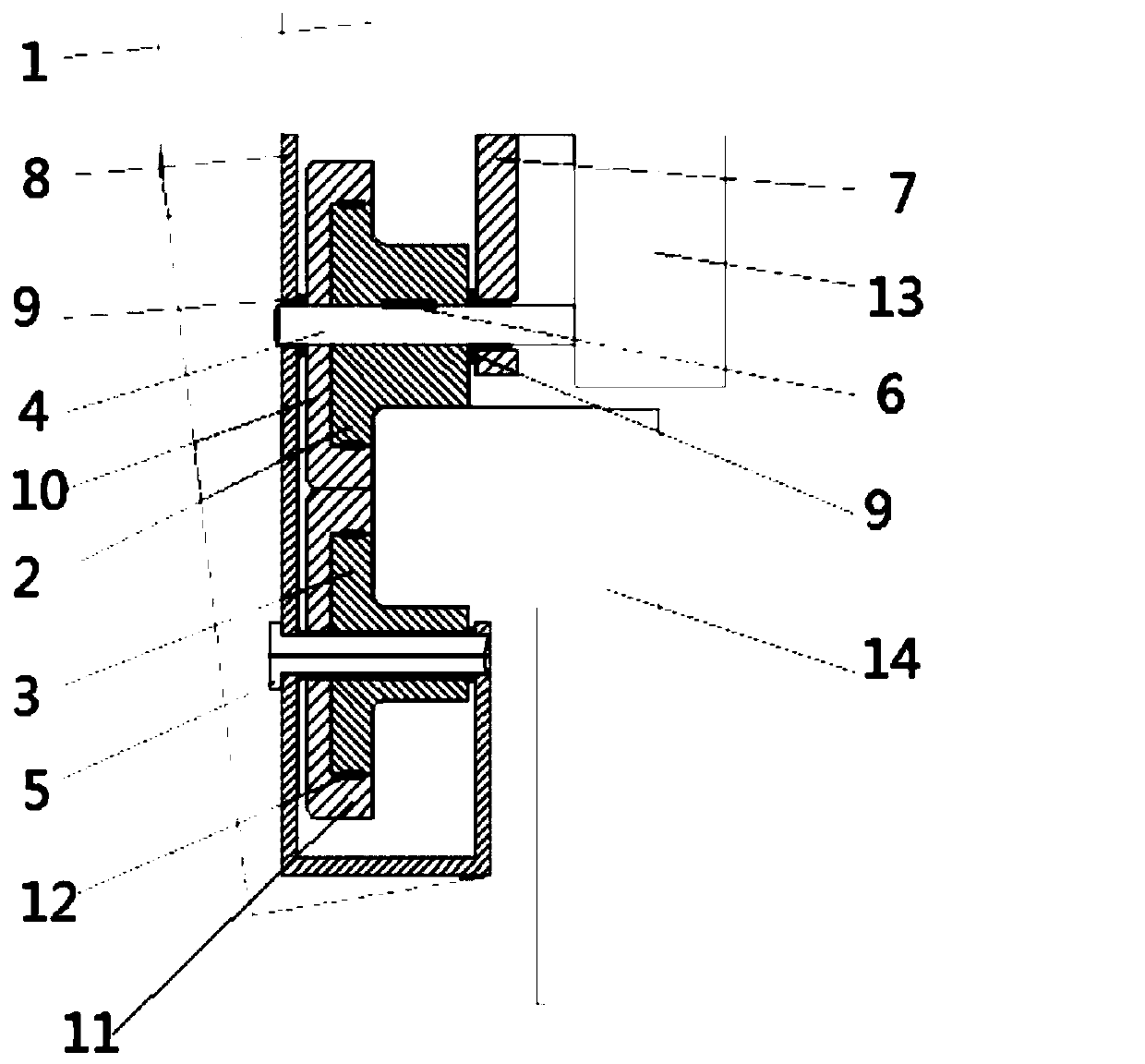
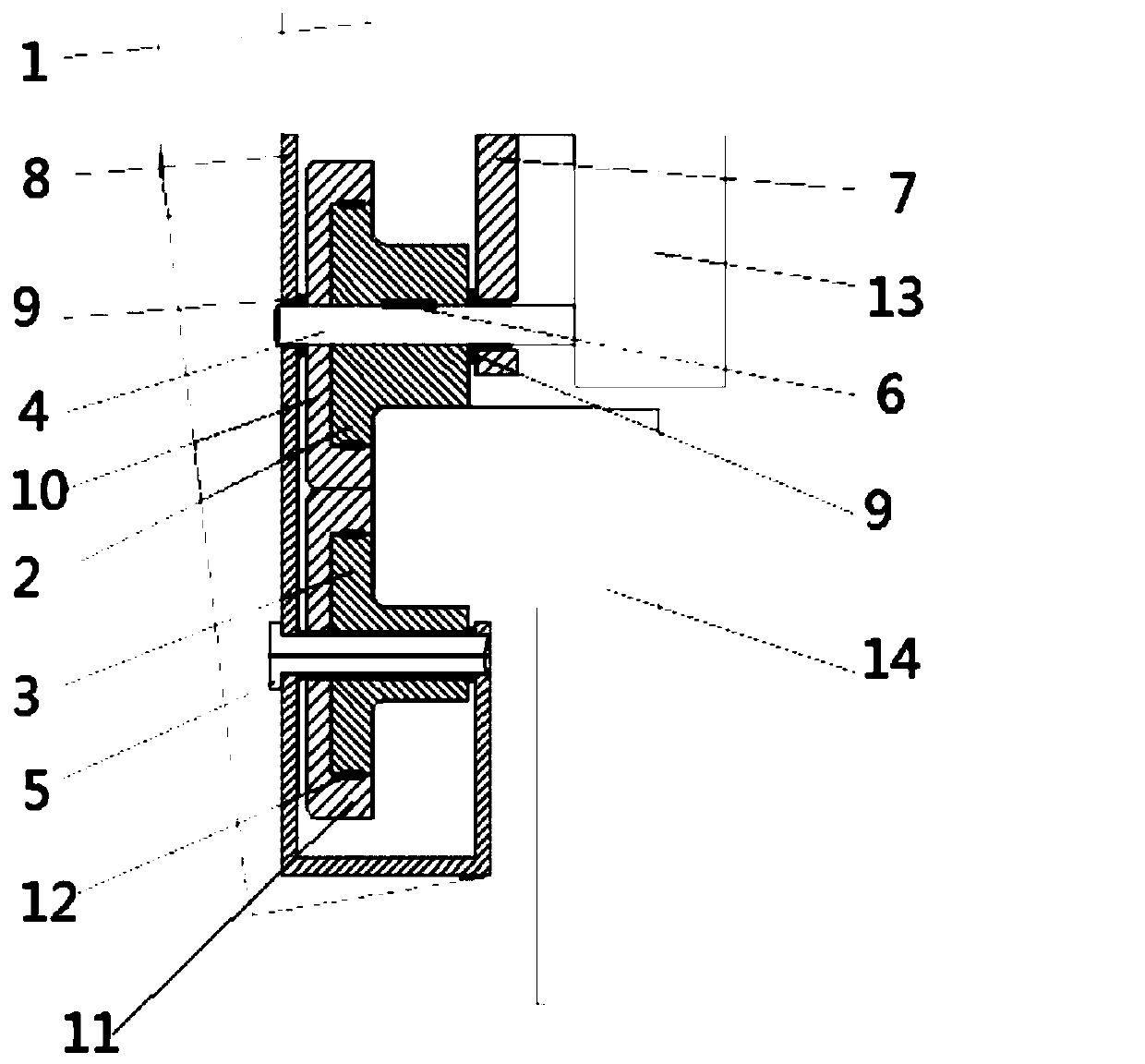
[0030] Embodiment: A wire winding robot without meshing transmission, including several walking trolleys and several power devices. The flange wheel 2 and the reverse tread flange wheel 3 are respectively rotatably installed on the vehicle body 1, the active tread flange wheel 2 and the reverse tread flange wheel 3 are meshed for transmission, and the active tread flange wheel 2 and the reverse tread flange wheel The circumferential surface of the flange wheel 3 can roll respectively on the two opposite side walls of the track of the prefabricated winding robot track 14 of the frame to be wound, and the flange steps of the active tread flange wheel 2 and the reverse tread flange wheel 3 The surface is close to the outer end face of the frame rail, and several power devices provide rotational power to the active tread flange wheel 2 and the reverse tread flange wheel 3 respectively forming the trolley.

[0031] When the prefabricated winding robot track 14 of the frame to be wo...


PUM


Abstract

The invention discloses a non-engaged-transmission steel wire winding robot. The non-engaged-transmission steel wire winding robot comprises multiple walking trolleys and multiple power devices. Eachwalking trolley comprises a trolley body, a drive step face flange wheel and a reverse step face flange wheel, wherein the drive step face flange wheel and the reverse step face flange wheel can be rotationally installed on the trolley body, the drive step face flange wheel and the reverse step face flange wheel are in engaged transmission, the circumferential face of the drive step face flange wheel and the circumferential face of the reverse step face flange wheel can be wrapped on the rail two opposite side walls of a prefabricated winding robot rail of a to-be-wound rack in a rolling manner, and the flange step face of the drive step face flange wheel and the flange step face of the reverse step face flange wheel abut against the outer side end face of the rack rail. The multiple powerdevices provide rotating power through the drive step face flange wheels and the reverse step face flange wheels forming the trolleys correspondingly. By means of the non-engaged-transmission steel wire winding robot, the transmission trouble caused by elastic deformation of the to-be-wound rack in the pre-tightening winding process is fundamentally saved, and the walking reliability of the walking trolleys is improved.

Description

technical field [0001] The invention relates to a winding device, in particular to a non-meshing transmission steel wire winding robot. Background technique [0002] Winding technology is one of the important directions for the development of prestressed structures. Its characteristic is that it fundamentally solves the stress concentration phenomenon on the main bearing parts and improves the fatigue life of the wound workpiece. Take the winding load-bearing frame as an example; the frame to be wound is fixed on a rotary platform, and rotates with the rotary platform to wind the wire onto the frame. If the frame is too large (tens of meters long), too heavy (hundreds, thousands or even tens of thousands of tons), the structure, size, load-bearing, operating speed and other aspects of the rotary platform cannot meet the construction requirements. Therefore, a winding robot was invented—that is, a robot with a relatively small tonnage (several tons) revolves around a large w...

Claims


Application Information

Patent Timeline
IPC IPC(8): B65H81/00B25J11/00
Inventor 李晓予颜永年陈振东
Owner KUNSHAN YONGNIAN ADVANCED MFG TECH
Learn More