Heat dissipating device, heat dissipating system and car

A technology of heat dissipation device and heat exchange device, which is used in heat exchange equipment, lighting and heating equipment, and coolant flow control, etc. The effect of uneven heat dissipation

Active Publication Date: 2019-06-07
ZHEJIANG GEELY AUTOMOBILE RES INST CO LTD +1
View PDF9 Cites 0 Cited by
  • Summary
  • Abstract
  • Description
  • Claims
  • Application Information

AI Technical Summary

Problems solved by technology

[0003] Due to the fixed structure of the existing radiator design scheme, no matter how the required heat dissipation of the heating element changes, the performance ...

Method used


Image

  • Heat dissipating device, heat dissipating system and car
  • Heat dissipating device, heat dissipating system and car
  • Heat dissipating device, heat dissipating system and car

Examples


Embodiment 1

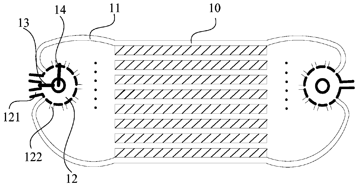
[0058] Such as figure 1 As shown, there is one multi-way valve 12, the first ports 121 of the multi-way valve 12 are respectively connected to the outlets of the cooling pipelines of the heating devices, and the second ports 122 of the multi-way valve 12 are respectively connected to the inlets of the heat pipes 10 , the outlet ends of the heat pipes 10 are respectively connected to the inlets of the cooling pipelines of the heat generating devices.

[0059] In the embodiment of the present application, the multi-way valve 12 is applied at the inlet of each cooling pipe 10, wherein the multi-way valve 12 is provided with two first ports 121 for liquid intake, and between the two first ports 121 A fixed partition 13 is set; a plurality of second ports 122 are set for liquid outlet, and a movable partition 14 is set between a plurality of second ports 122, and the second port 122 communicates with the heat dissipation pipe 10 through the connecting pipe 11, thereby Cooling liqu...

Embodiment 2

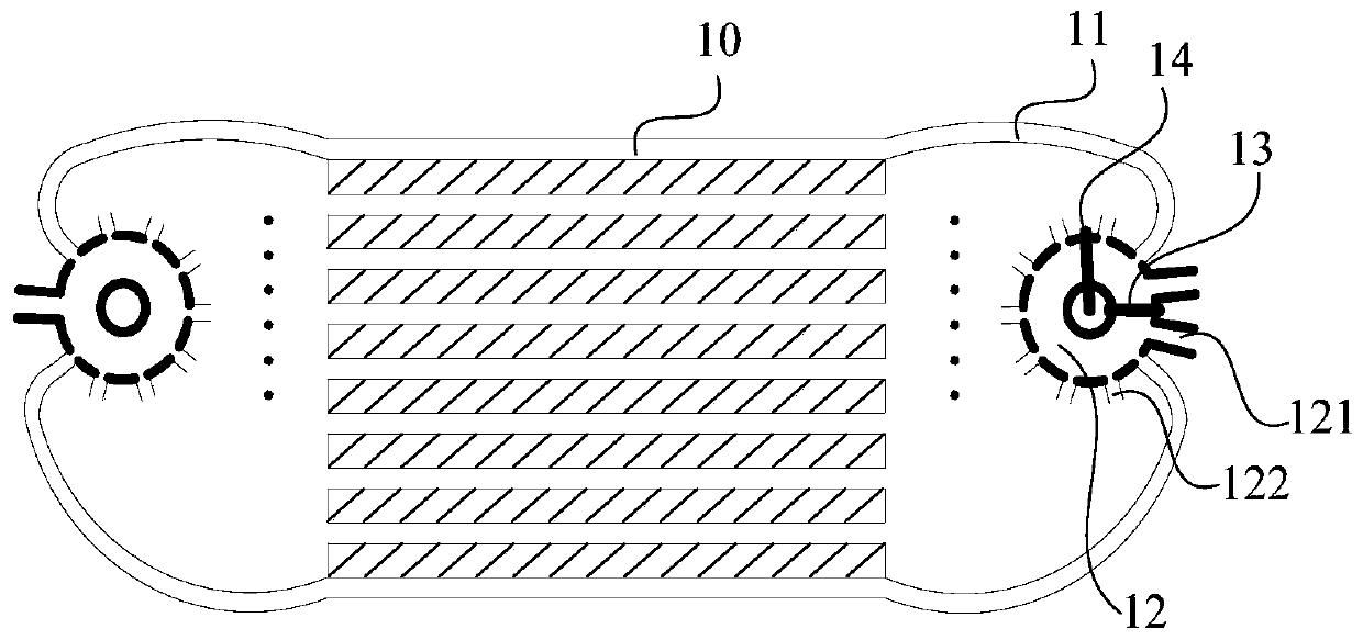
[0062] Such as figure 2 As shown, there is one multi-way valve 12, the first ports 121 of the multi-way valve 12 are respectively connected to the inlets of the cooling pipelines of the heating devices, and the second ports 122 of the multi-way valve 12 are respectively connected to the outlets of the cooling pipes 10 , the inlet ends of the heat pipes 10 are respectively connected to the outlets of the cooling pipelines of the heat generating devices.

[0063] In the embodiment of the present application, the multi-way valve 12 is applied at the outlet of each heat dissipation pipe 10, wherein the multi-way valve 12 is provided with two first ports 121 for liquid outlet, and between the two first ports 121 A fixed partition 13 is set; a plurality of second ports 122 are set for liquid intake, and a movable partition 14 is set between a plurality of second ports 122, and the second port 122 communicates with the heat dissipation pipe 10 through the connecting pipe 11, thereby...

Embodiment 3

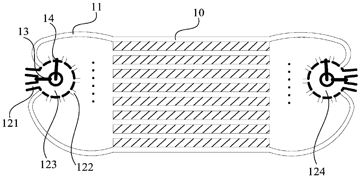
[0065] Such as image 3 As shown, there are two multi-way valves, namely the first multi-way valve 123 and the second multi-way valve 124;

[0066] The first port 121 of the first multi-way valve 123 is connected with the outlet of the cooling pipeline of each heat-generating device respectively, and the second port 122 of the first multi-way valve 123 is connected with the inlet of each radiating pipe 10 respectively, and each radiating pipe 10 The outlet ports are respectively connected to the inlets of the cooling pipelines of the heating devices;

[0067] The first port 121 of the second multi-way valve 124 is connected with the inlet of the cooling pipeline of each heat-generating device respectively, and the second port 122 of the second multi-way valve 124 is connected with the outlet of each radiating pipe 10 respectively, and the outlet of each radiating pipe 10 The inlet ports are respectively connected to the outlets of the cooling pipelines of the heating devices;...


PUM


Abstract

The invention relates to the technical field of heat dissipaters, in particular to a heat dissipating device, a heat dissipating system and a car. The heat dissipating device comprises a plurality ofheat dissipating pipes and at least one multi-way valve. Each multi-way valve comprises at least two first openings and i second openings. The first openings are used for being connected with a cooling pipeline of a heating device. The second openings communicate with the heat dissipating pipes through connecting pipes correspondingly. The interior of each multi-way valve is divided into multiplemutual independent areas. Each area communicates with at least one first opening and n second openings, wherein n is equal to 0, 1 to i, and i is an integer not smaller than 2. When a certain loop requires for the large heat dissipating amount while the other loop requires for the small heat dissipating amount, by means of the multiple mutual independent areas divided in the interior of each multi-way valve, free distribution of the heat dissipating pipes in the loops can be achieved, and then difference of flow of cooling liquid of the cooling loops of the whole heat dissipating device is achieved.

Description

technical field [0001] The invention relates to the technical field of radiators, in particular to a radiator, a radiator system and an automobile. Background technique [0002] The existing flat-tube-finned radiator is a common liquid-cooled radiator, which mainly includes cooling circuits, flat tubes, liquid collectors and cooling fins, and several fixed partitions are added to the radiator liquid collectors And the corresponding number of water outlets, and then separate the fixed passage of the same radiator for cooling additional heat sources. [0003] Due to the fixed structure of the existing radiator design scheme, no matter how the required heat dissipation of the heating element changes, the performance of the radiator used for the cooling circuit of the heating element is always constant, which will cause the radiator to dissipate heat. Performance is unevenly distributed. Contents of the invention [0004] The object of the present invention is to provide a h...

Claims


Application Information

Patent Timeline
IPC IPC(8): F01P11/00F01P7/14F28F1/12
Inventor 王宇梁长裘苏醒丁智
Owner ZHEJIANG GEELY AUTOMOBILE RES INST CO LTD
Why Eureka
Try Eureka