Heat dissipation power device for power engineering

A technology of power engineering and power devices, applied in the field of electric power, can solve problems such as inability to dissipate heat, and achieve the effects of avoiding uneven heat dissipation, multiple heat dissipation spaces and heat dissipation effects

Inactive Publication Date: 2020-11-06
黄东梅
View PDF0 Cites 0 Cited by
  • Summary
  • Abstract
  • Description
  • Claims
  • Application Information

AI Technical Summary

Problems solved by technology

[0005] In order to solve the above-mentioned technology, when the heat sink dissipates heat through copper sheets, since the arrangement of copper sheets usually stacks multiple sheets together to dissipate heat through the lateral outer contour, the heat can only be dissipated through a small number of exposed surfaces, while A very large part of the copper sheet in the combined copper sheet can only play the role of heat conduction and cannot dissipate heat

Method used


Image

  • Heat dissipation power device for power engineering
  • Heat dissipation power device for power engineering
  • Heat dissipation power device for power engineering

Examples


Embodiment 1

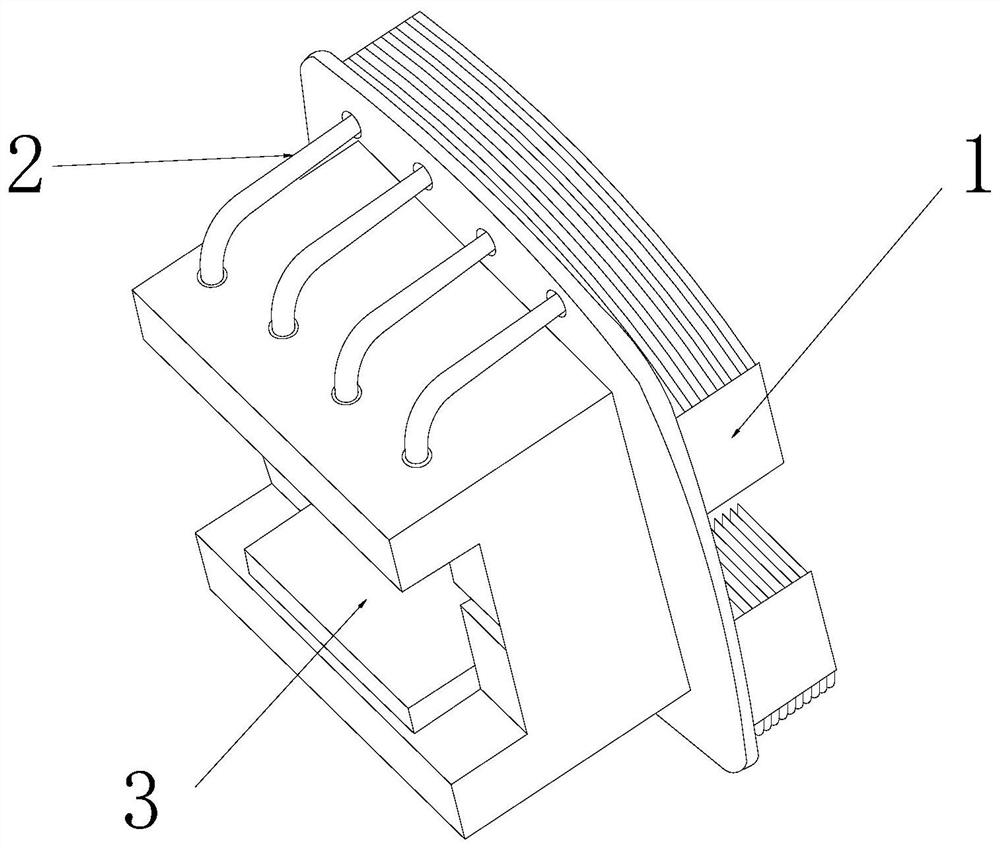
[0026] as attached figure 1 To attach Figure 5 Shown:

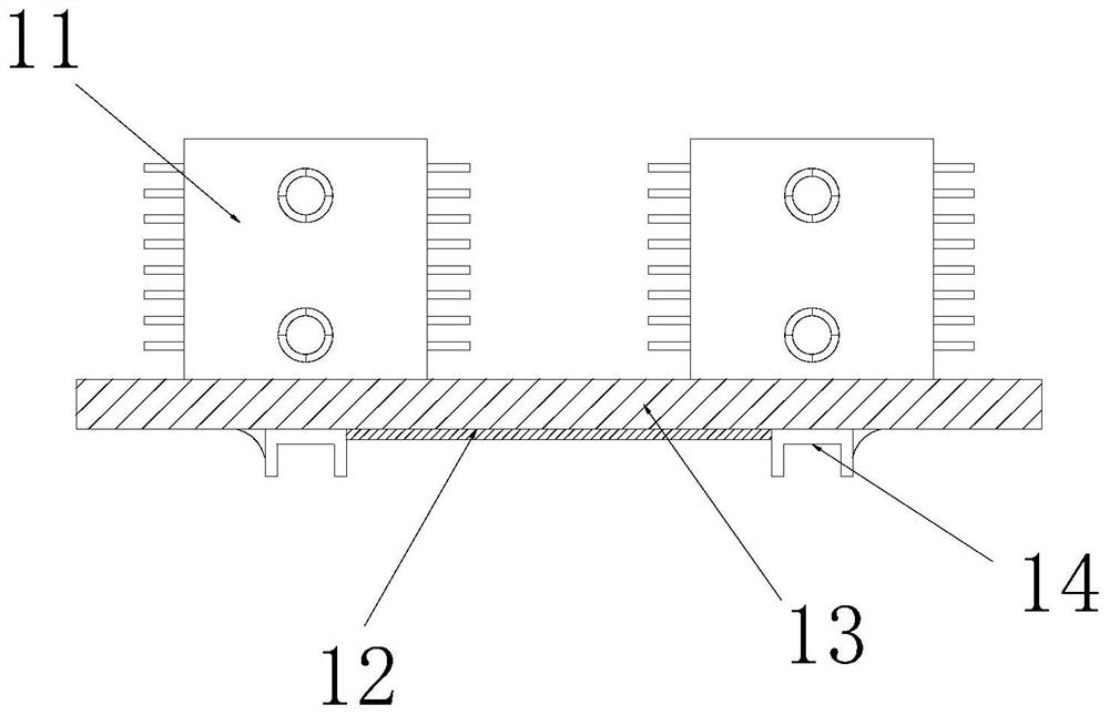
[0027] The invention provides a heat dissipation power device for electric power engineering, the structure of which includes a heat dissipation seat 1, a water guide pipe 2, and an embedded copper block 3. The water guide pipes 2 are evenly distributed on the left and right ends of the embedded copper block 3; the heat sink 1 includes a heat dissipation mechanism 11, a thermally conductive coating 12, an embedded solid block 13, and an inlay groove 14, and the heat dissipation mechanism 11 is symmetrically installed on the inlay On the left and right sides of the upper end of the groove 14, the thermally conductive coating 12 is evenly applied on the lower end surface of the embedding block 13 and fitted with the embedding groove 14, and the lower end surface of the embedding block 13 is embedded with the embedding groove 14, The inlay groove 14 is located right below the heat dissipation mechanism 11 .

[0028] Wher...

Embodiment 2

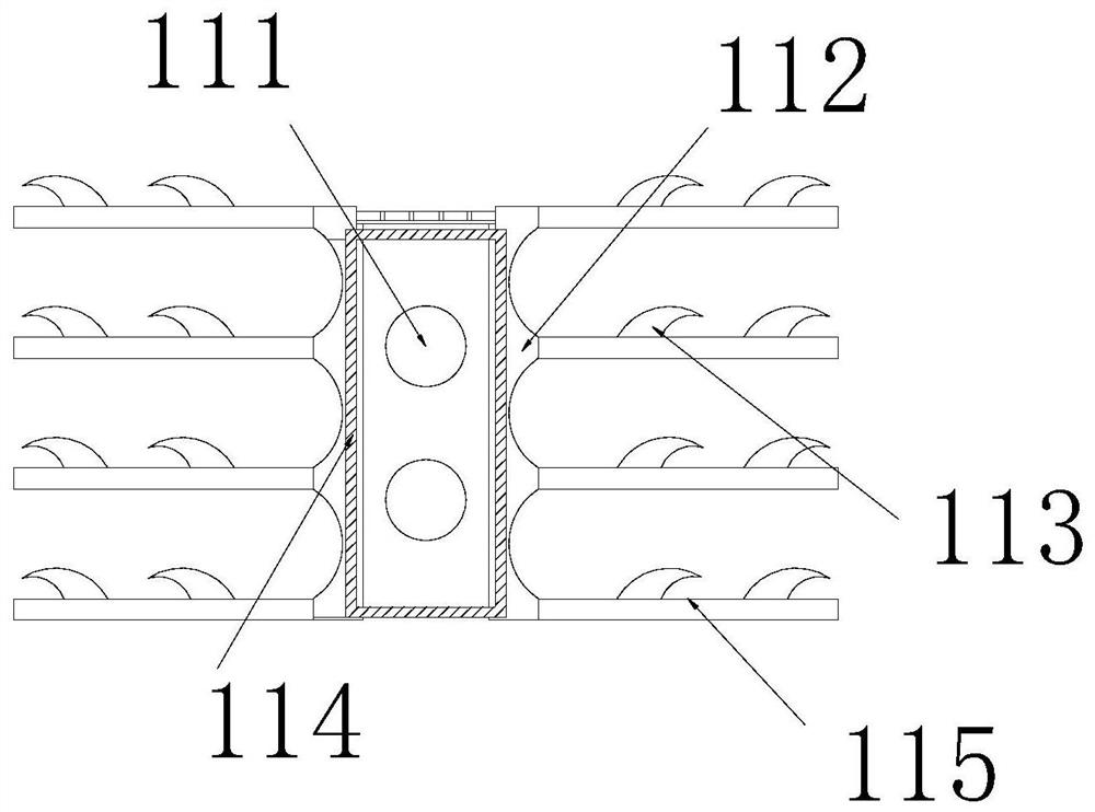
[0034] as attached Figure 6 To attach Figure 8 As shown: the heat dissipation pipe 111 includes a dispersion block 11a, a fitting groove 11b, a second heat dissipation port 11c, a connecting rod 11d, and a blocking block 11e, and the dispersion block 11a is symmetrically installed on the left and right sides of the heat dissipation pipe 111. The fitting groove 11b is inlaid and installed on the outer end surface of the heat dissipation pipe 111, the second cooling openings 11c are evenly distributed on the laterally outer end surface of the dispersing block 11a, and the connecting rod 11d is evenly inlaid and installed on the laterally outer end surface of the blocking block 11e and connected with The dispersing block 11a fits together, the barrier block 11e is located at the center of the dispersing block 11a, and the number of the second cooling openings 11c just matches the number of connecting plates 115, which can evenly conduct heat to the connecting plate 115 in vivo...


PUM


Abstract

The present invention discloses a heat dissipation power device for power engineering. The heat dissipation power device structurally comprises a heat dissipation base, water guide pipes and built-incopper blocks, the lower end face of the heat dissipation base is installed on the outer side faces of the upper ends of the built-in copper blocks in an attached mode, and the water guide pipes are evenly distributed on the left end faces and the right end faces of the built-in copper blocks; the heat dissipation base comprises heat dissipation mechanisms, a heat conduction coating, an embedded fixing block and an embedded groove. The heat dissipation mechanisms are symmetrically installed on the left and right sides of the upper end of the embedded groove. The heat conduction coating is uniformly smeared on the end surface of the lower side of the embedded fixing block and is attached to the embedded groove; the embedded groove is fixedly embedded in the lower end surface of the embeddedfixing block; and the embedded groove is located under the heat dissipation mechanisms. By means of the specific heat capacity of water, heat is evenly conducted into the connecting plates and the heat dissipation block body, the heat is transmitted into the second built-in copper block through the second water flowing pipe, finally, the high temperature of the water is dissipated through a hollowed-out block, and more heat dissipation space and heat dissipation effect are obtained by means of embedding fit of the multiple sets of connecting plates and the heat dissipation block.

Description

technical field [0001] The invention belongs to the field of electric power, and more specifically, relates to a cooling power device for power engineering. Background technique [0002] The heat dissipation power device used in electric power engineering is mainly assembled on the power hub. By embedding the copper sheet on the heat sink, the good thermal conductivity of the copper sheet is used to dissipate the heat through the heat sink, thereby achieving the effect of reducing the temperature. . [0003] Based on the above inventors' discovery, the existing methods mainly have the following disadvantages, for example: when the heat sink is dissipating heat through copper sheets, since the arrangement of copper sheets usually stacks multiple sheets together to dissipate heat through the lateral outer contour, As a result, the heat can only be dissipated through a small number of exposed surfaces, and a large part of the copper sheets in the combined copper sheet can only...

Claims


Application Information

Patent Timeline
Patent Type & Authority Applications(China)
IPC IPC(8): H02B1/56
CPCH02B1/56
Inventor 黄东梅
Owner 黄东梅
Why Eureka
Try Eureka