Mutual inductor device for breaker

A technology of transformers and circuit breakers, which is applied in the field of electronic molded case circuit breakers, can solve the problems of inconvenient heat dissipation of transformers, cumbersome installation process, inconvenient installation, etc., and achieve labor cost saving, fast and convenient installation, and quick replacement Effect

Active Publication Date: 2016-12-14
DELIXI ELECTRIC
View PDF3 Cites 0 Cited by
  • Summary
  • Abstract
  • Description
  • Claims
  • Application Information

AI Technical Summary

Problems solved by technology

[0003] (1) By adding a structure that can be used for riveting to the structure of the transformer, the transformer and the base of the transformer are riveted together to play the role of positioning the transformer. This method is not convenient for installation, and the installation process is cumbersome, and there are Risk of loose riveting
[0004] (2) Fix the transformer in the base by pouring glue. This way makes the transformer permanently fixed in the base. The surrounding of the transformer is filled with solid glue, which is not convenient for heat dissipation of the transformer or replacement of the transformer. When the transformer is unqualified, the whole set can only be scrapped, which is very wasteful and uneconomical

Method used


Image

  • Mutual inductor device for breaker
  • Mutual inductor device for breaker
  • Mutual inductor device for breaker

Examples


Embodiment 1

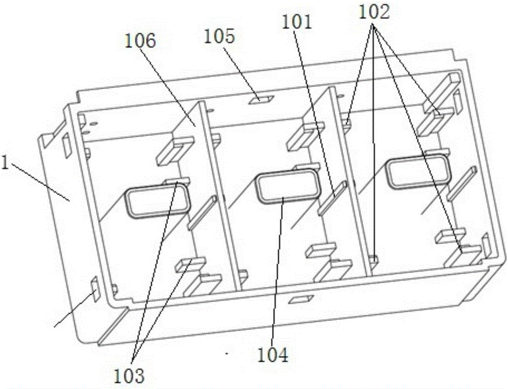
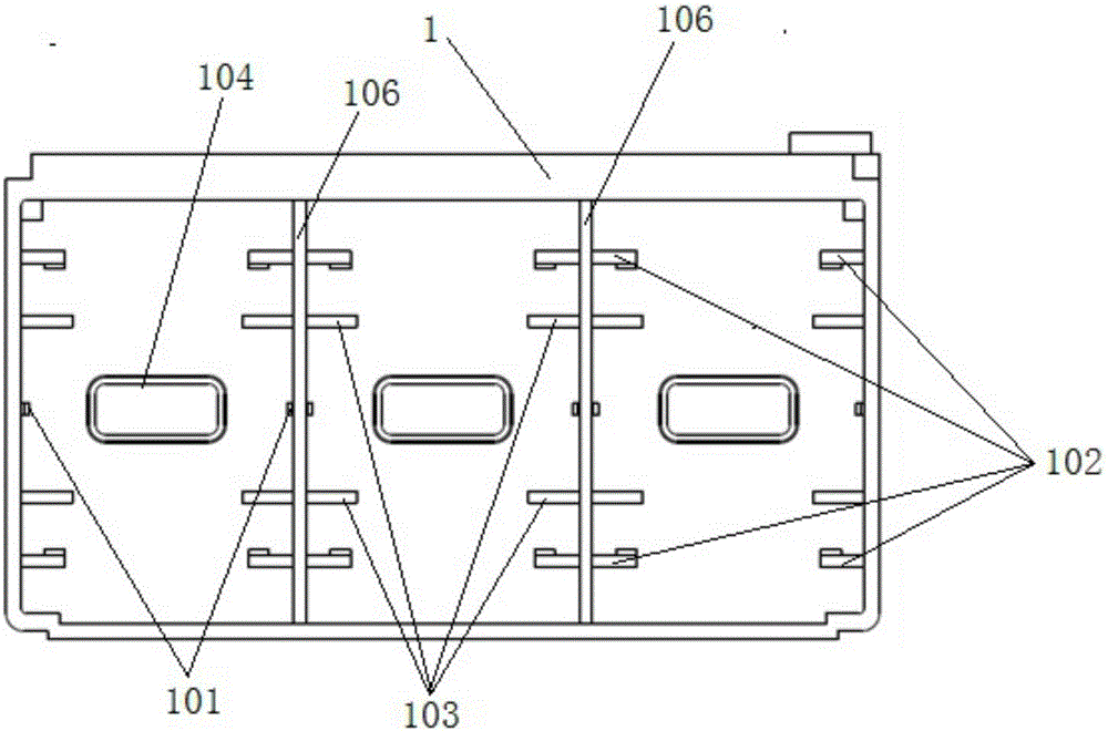
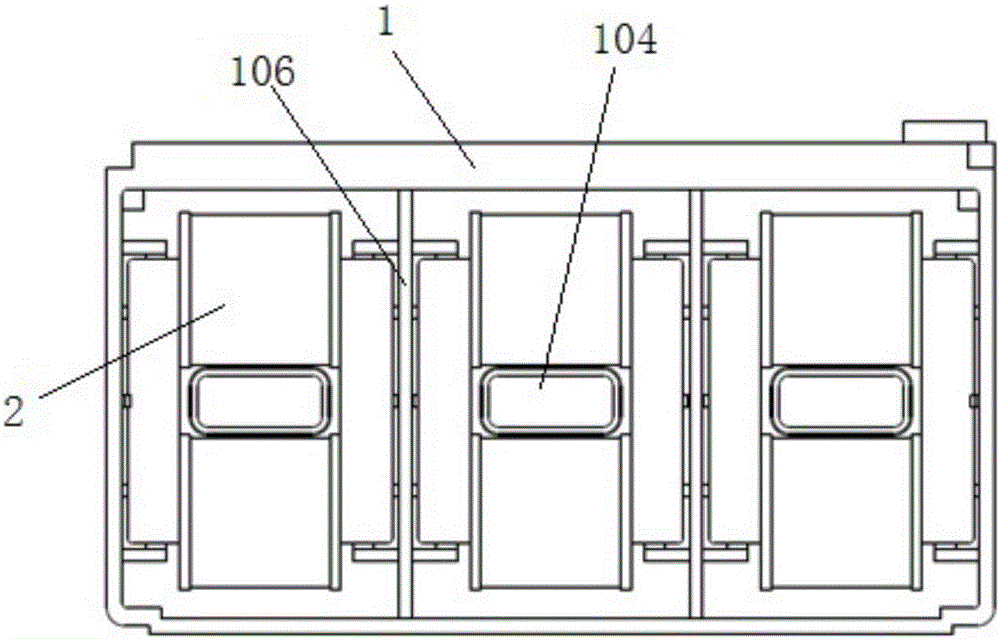
[0042] A transformer device for a circuit breaker, such as Figure 1-9 As shown, it includes a base 1 and a cover plate 3 that match each other. The top of the base 1 is open, and at least one chamber is provided in the base 1. In this embodiment, the base 1 is preferably divided into three chambers by two partitions 106. Each chamber is provided with a transformer 2, the transformer 2 has a mounting surface, and the inside of each chamber and the bottom of the cover plate 3 opposite to the chamber has a limit rib that cooperates with the mounting surface, and the limit rib and the mounting surface Cooperate to fix the transformer 2 in the base 1.

[0043] Such as Figure 5-6 As shown, the preferred transformer in this embodiment is composed of a coil 23 and an iron core, the iron core is a rectangular iron core, and the iron core part exposed outside the coil 23 is a first iron core subsection 21 and a second iron core subsection 22, Located on both sides of the coil 23 res...


PUM


Abstract

The invention relates to a mutual inductor device for a breaker. The device comprises a base (1) and a cover plate (3) which are matched with each other, wherein the top of the base (1) is opened, and at least one cavity is formed in the base (1); a mutual inductor (2) is arranged in each cavity, and is provided with a mounting surface; a spacing rib matched with the respective mounting surface is arranged inside each cavity and the bottom of the cover plate (3) opposite to the cavity, and is matched with the mounting surface, so that the mutual inductor (2) is fixed in the base (1). Compared with the prior art, the mutual inductor device is quick and convenient to mount, and has the advantages of saving labor cost in the assembling process, effectively improving the assembly work efficiency and the like.

Description

technical field [0001] The invention belongs to the field of electronic molded case circuit breakers, and in particular relates to a transformer device of a circuit breaker. Background technique [0002] At present, the transformer installation methods of electronic molded case circuit breakers on the market are as follows: [0003] (1) By adding a structure that can be used for riveting to the structure of the transformer, the transformer and the base of the transformer are riveted together to play the role of positioning the transformer. This method is not convenient for installation, and the installation process is cumbersome, and there are Risk of loose riveting. [0004] (2) Fix the transformer in the base by pouring glue. This way makes the transformer permanently fixed in the base. The surrounding of the transformer is filled with solid glue, which is not convenient for heat dissipation of the transformer or replacement of the transformer. When the transformer is un...

Claims


Application Information

Patent Timeline
Patent Type & Authority Applications(China)
IPC IPC(8): H01F38/30H01F27/06H01H71/02
CPCH01F27/06H01F38/30H01F2038/305H01H71/02
Inventor 莫洪春王砚波宋志文曾玲
Owner DELIXI ELECTRIC
Why Eureka
Try Eureka