Blast furnace slag dry granulation bin

A dry granulation and blast furnace slag technology, applied in the field of granulation silo, can solve the problems that the flight time of slag particles is difficult to reach 1s, the length of the silo body and the cooling time are difficult to choose, and the cooling time of slag particles cannot be provided. Solve the effect of storage difficulty, transportation difficulty and volume reduction

Active Publication Date: 2015-07-29
无锡市东方环境工程设计研究所有限公司
View PDF6 Cites 0 Cited by
  • Summary
  • Abstract
  • Description
  • Claims
  • Application Information

AI Technical Summary

Problems solved by technology

[0005] Chinese patent 201120390445.7 proposes an anti-sticking granulated heat exchange chamber, which can take into account the utilization of the active components of the slag product and the recovery of waste heat, but the disadvantage is that it is difficult to choose between the length of the chamber body and the cooling time, although the chamber body The length is about 10 meters which can be tolerated by the general site, and the flight time of slag particles in it is difficult to reach 1s. For slag particles with a diameter of about 2mm, it takes at least 1s~2s to form solid or semi-solid particles. Can provide enough slag particle cooling time
A liquid slag processing device disclosed in invention patent 201110311686.2 also uses a similar rectangular static granulation bin, which also has the problems of too long length and too large volume
[0006] In addition, the dry granulation process also includes more auxiliary equipment, such as conveying equipment, waste heat recovery equipment, etc. The equipment is large and bulky, which will inevitably cause excessive heat loss, resulting in reduced thermal efficiency and increased energy consumption, thus losing the value of use

Method used


Image

  • Blast furnace slag dry granulation bin

Examples


Embodiment Construction

[0027] The present invention will be further described in detail below in conjunction with the accompanying drawings and specific embodiments.

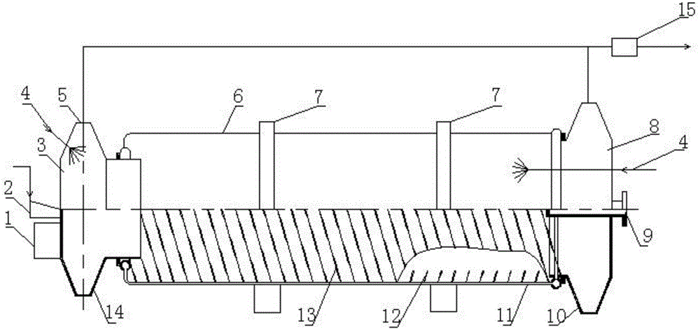
[0028] A blast furnace slag dry granulation bin, its structure is as follows figure 1 As shown, it includes interconnected front warehouse 3, middle warehouse 6 and rear warehouse 8, the front end of the front warehouse 3 is provided with a feed port, the bottom of the rear warehouse is provided with a discharge port 10, and the front warehouse 3 The rear end is connected with the front end of the middle warehouse 6 by a mechanical seal, and the rear end of the middle warehouse is connected with the front end of the rear warehouse by a mechanical seal. The middle warehouse is a rotatable device, while the front and rear warehouses cannot be turned.

[0029] The front end of the front warehouse 3 is provided with a slag chute 2 and a granulator 1, the upper part of the front warehouse is provided with an accelerator injection device 4...


PUM


Abstract

The invention discloses a dry-process blast furnace slag granulating bin. The dry-process blast furnace slag granulating bin comprises a front bin, a middle bin and a rear bin which are communicated with one another, wherein the front end of the front bin is provided with a molten slag chute and a granulator; the rear end of the front bin and the front end of the middle bin are connected in a mechanical sealing manner; the middle bin is a barrel body structure, is supported by a supporting frame with fine adjustment of the inclination and is horizontally placed; the barrel-type middle bin is driven by a driving mechanism outside a bin body to rotate by adopting the central axis of a barrel body as a central axis; membrane type pipes are densely distributed on the wall surface of the middle bin, a spiral conveying and cooling pipe is arranged in an inner cavity of the barrel-type middle bin, and the rear end of the middle bin and the front end of the rear bin are connected in a mechanical sealing manner; a discharging opening is arranged at the bottom part of the tail end of the rear bin, and the center of the tail end of the rear bin is provided with a heat-exchange medium steam-water entering and exiting opening. The dry-process granulating bin disclosed by the invention has the advantages that on the basis of no bonding to slag and full utilization of active components of a slag product, the waste-heat recovery rate of the blast furnace slag can be improved, the operating process is simplified, the size of a bin body is shrunk and the energy consumption and the investment are reduced.

Description

technical field [0001] The invention relates to the technical field of energy saving and environmental protection of metallurgy, in particular to a granulation bin used for crushing high-temperature liquid slag and recovering waste heat. Background technique [0002] Blast furnace slag is a by-product of ironmaking. The discharge temperature of blast furnace slag is about 1400°C. The heat contained in each ton of blast furnace slag reaches 1.8GJ, which is equivalent to the heat contained in 64kg of standard coal. At the same time, the waste slag finally discharged from the blast furnace slag treatment process contains very useful active components. Although the active components are different due to different treatment processes, they can all be used as raw materials for road construction, cement and other industries. [0003] The traditional main method for treating blast furnace slag is the wet water quenching method. This method is simple in process and can recycle waste ...

Claims


Application Information

Patent Timeline
Patent Type & Authority Patents(China)
IPC IPC(8): C21B3/06
CPCY02W30/543Y02W30/50
Inventor 谈庆张鹏王红军徐长存雷震东郭徽
Owner 无锡市东方环境工程设计研究所有限公司
Why Eureka
Try Eureka