Hot conflux main pipe residual heat reclamation and utilization system using gas medium as hot source

A waste heat recovery and parent control technology, applied in heating systems, applications, waste heat treatment, etc., can solve the problems of difficult to achieve waste heat recovery, low waste heat recovery rate, and heavy maintenance workload, and achieve easy operation and maintenance. Simple system operation , the effect of small footprint

Active Publication Date: 2007-11-28
SHANGHAI EAGLE NEW TECH ENG
View PDF0 Cites 3 Cited by
  • Summary
  • Abstract
  • Description
  • Claims
  • Application Information

AI Technical Summary

Problems solved by technology

[0002] Usually, the heat source of the waste heat recovery and utilization device whose heat source is gas medium is a one-to-one unit unit, that is, one hot air source is directly connected to one waste heat recovery and utilization device through the conveying pipeline, and there are multiple nearby hot air source sources and front generated hot air sources. In the case where the equipment has mutual backup, the one-to-one arrangement not only requires enough space, but also has poor mutual backup when the equipment that generates the heat source and the waste heat recovery device are deactivated alternately; in the case of a small-capacity heat source, the waste heat Recovery is not easy to realize, and the heat loss of multiple small-capacity waste heat recovery and utilization devices is generally greater than that of a single waste heat recovery and utilization device, the waste heat recovery rate is relatively low, and the recycling economy is poor; in addition, the operation and maintenance workload of multiple waste heat recovery and utilization devices Large and many spare parts

Method used


Image

  • Hot conflux main pipe residual heat reclamation and utilization system using gas medium as hot source
  • Hot conflux main pipe residual heat reclamation and utilization system using gas medium as hot source

Examples


Embodiment

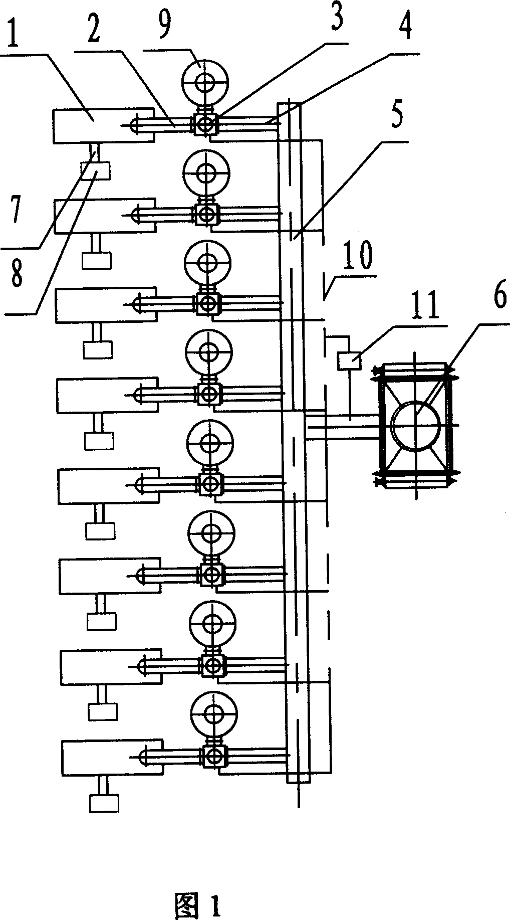
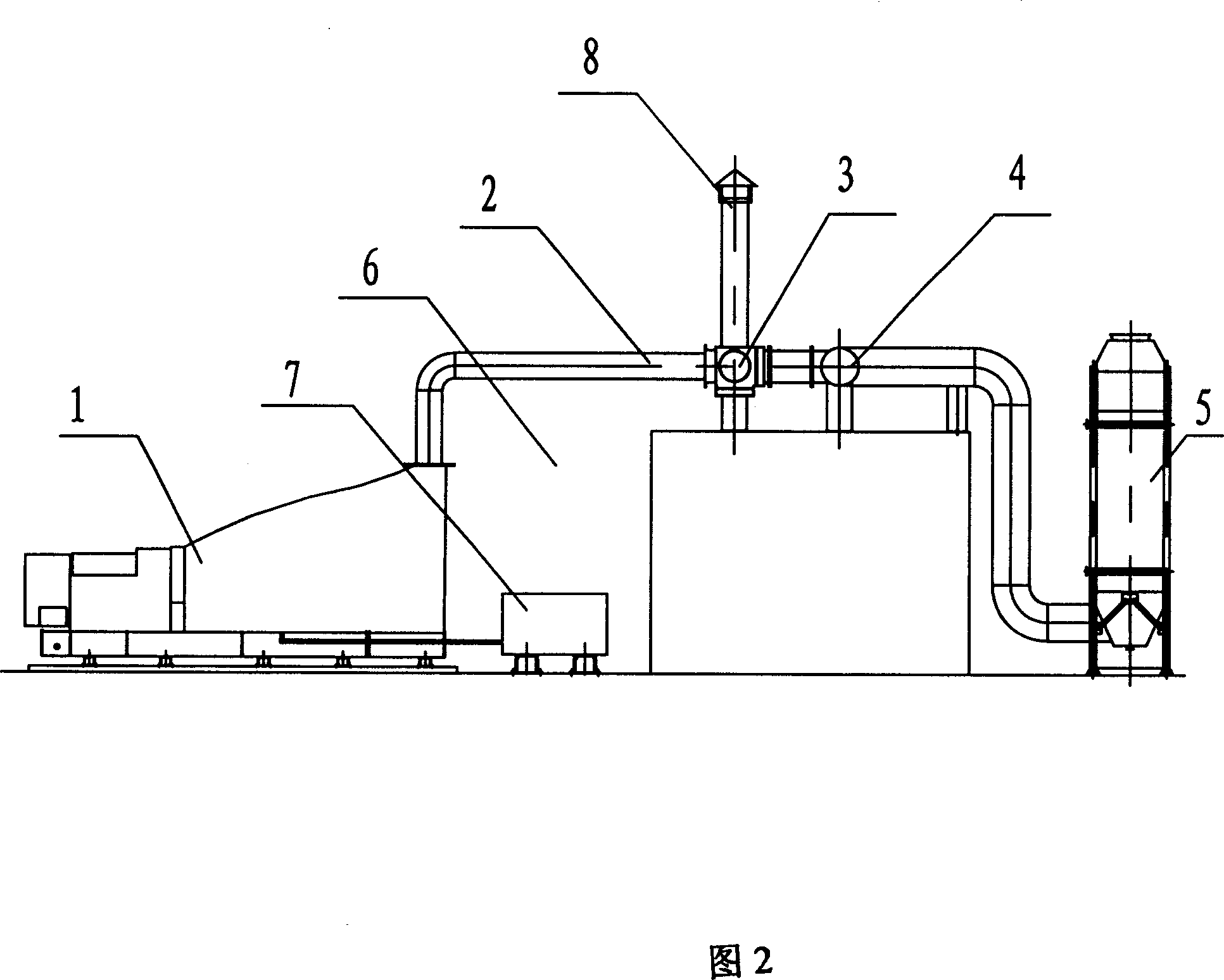
[0015] Take 8 diesel generators with a capacity of 1000kW as heat source 1 as an example:

[0016] 8 diesel generators 1 with a capacity of 1000kW, and the capacity of the exhaust heat source is 232.4M 3 / min, and the temperature of the hot air source is 449°C. In the planning and construction of the plant, the hot air source discharged from the generator is directly connected to the atmosphere, and the site where the waste heat recovery device is installed is not considered. Outside the generator building is the road in the factory area. There is an open space at one end of the generator building. Now the heat from 8 diesel generators 1 with a capacity of 1000kW is recovered into a waste heat recovery device.

[0017] As shown in Figures 1 and 2, it is a schematic diagram of the waste heat recovery and utilization system of the heat confluence main pipe with the heat source as the gas medium. The exhaust hot gas sources of the eight generators are respectively passed through ...


PUM


Abstract

The invention relates to a thermal confluence bus-piping waste heat recovery and utilization system, whose thermal source is air medium. It is characterized in that at least two thermal air sources are connected with the channel of thermal air source respectively; each channel of thermal air source is connected one way of three-way wind door; another channel of three-way wind door is connected with the bus pipe of thermal confluence by connecting pipes; the bus pipe of thermal confluence is connected with the waste heat recovery device; the third way of three-way wind door is connected with by-pass channel; the protection device of generating device of thermal air source can be assigned on the channel of thermal air channel directly; the control equipment of thermal confluence is connected with the generating device of thermal air source, the three-way wind door and controlling and measuring component on the waste heat recovery and utilization device by control circuit. The merit of invention is that multiple thermal air sources are combined to enter into a waste heat recovery and utilization device so that waste recovery is realized easily and it is provided with high recovery efficiency, compact structure, small occupied area, easy assignment, easy running and maintenance and few spare parts.

Description

technical field [0001] The invention relates to a waste heat recovery and utilization system of a heat confluence bus pipe with gas medium as the heat source, which can be used in the occasion where multiple parallel heat sources are merged into a set of waste heat recovery and utilization device through the heat confluence main pipe, and can be jointly supplied with heat energy by multiple parallel heat sources at the same time Or only part of the heat source provides heat energy, which belongs to the technical field of waste heat recovery and utilization devices. Background technique [0002] Usually, the heat source of the waste heat recovery and utilization device whose heat source is gas medium is a one-to-one unit unit, that is, one hot air source is directly connected to one waste heat recovery and utilization device through the conveying pipeline, and there are multiple nearby hot air source sources and front generated hot air sources. In the case where the equipment...

Claims


Application Information

Patent Timeline
Patent Type & Authority Applications(China)
IPC IPC(8): F24D12/00F24H8/00F27D17/00F28F7/00F01N5/02
CPCY02B30/102Y02T10/16Y02B30/00Y02P80/15Y02T10/12
Inventor 赵卫黎晓原杨淙煊朱彤李凤兰
Owner SHANGHAI EAGLE NEW TECH ENG
Why Eureka
Try Eureka