evaporative cooling motor

A technology for evaporative cooling and cooling of working fluids, applied in cooling/ventilation devices, electromechanical devices, electrical components, etc., can solve the problems of uneven heat dissipation of evaporative cooling motors, large material consumption, long axial dimensions, etc., to avoid local heat dissipation. Decreased performance, good cooling effect, effect of reducing axial length

Active Publication Date: 2021-03-16
INST OF ELECTRICAL ENG CHINESE ACAD OF SCI
View PDF4 Cites 0 Cited by
  • Summary
  • Abstract
  • Description
  • Claims
  • Application Information

AI Technical Summary

Problems solved by technology

[0005] In order to solve the above-mentioned problems in the prior art, that is, in order to solve the problems of uneven heat dissipation, long axial dimension, large material consumption and low motor performance of the existing evaporative cooling motor, the present invention provides an evaporative cooling motor, The motor includes a housing, the housing has a first cavity for accommodating the stator and a second cavity above the first cavity, the first cavity has a liquid cooling medium, and the motor It also includes a condensing device arranged above the second cavity; wherein, the second cavity communicates with the first cavity and the condensing device respectively, so that the cooling working fluid enters the The second cavity and the condensing device are condensed into a liquid state in the condensing device and then flow back to the first cavity under the action of gravity; wherein, a concave structure is arranged on the outer peripheral surface of the stator, and the concave structure at least a portion of which is not opened to the inner peripheral surface of the stator

Method used


Image

  • evaporative cooling motor
  • evaporative cooling motor
  • evaporative cooling motor

Examples


Embodiment Construction

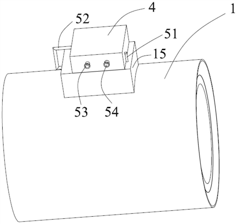
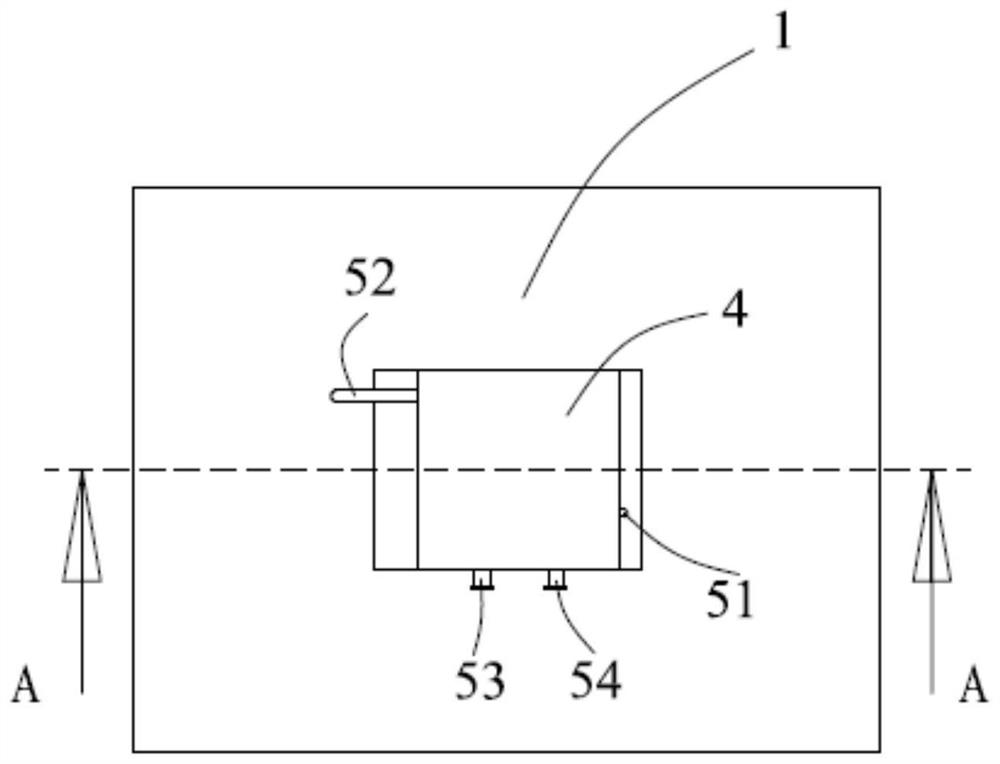
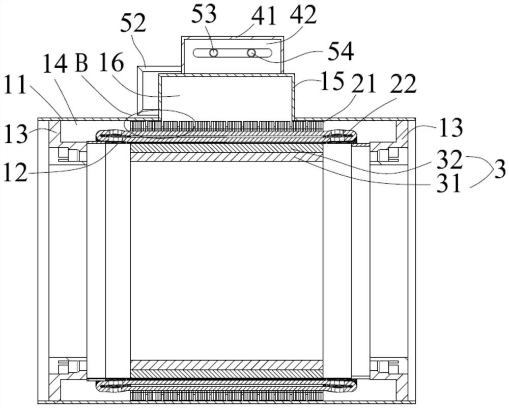
[0026] Preferred embodiments of the present invention are described below with reference to the accompanying drawings. Those skilled in the art should understand that these embodiments are only used to explain the technical principles of the present invention, and are not intended to limit the protection scope of the present invention.

[0027] It should be noted that, in the description of the present invention, terms such as "left", "right", "inner", "outer" and other indicated directions or positional relationships are based on the directions or positional relationships shown in the drawings, which It is for the convenience of description only, and does not indicate or imply that the device or element must have a specific orientation, be constructed and operate in a specific orientation, and thus should not be construed as limiting the present invention. In addition, the terms "first" and "second" are used for descriptive purposes only, and should not be understood as indic...


PUM


Abstract

The invention relates to the technical field of motors, particularly provides an evaporative cooling motor, and aims to solve the problems that an existing evaporative cooling motor is uneven in heatdissipation, relatively long in axial size, relatively large in material consumption and relatively low in motor performance. The motor comprises a shell; the shell is internally provided with a firstcavity for containing a stator and a second cavity located above the first cavity; the first cavity is internally provided with a liquid cooling working medium; the motor further comprises a condensing device arranged above the second cavity; the second cavity communicates with the first cavity and the condensing device, so that the cooling working medium sequentially enters the second cavity andthe condensing device after being changed into a gas state, is condensed into a liquid state in the condensing device and then flows back to the first cavity under the action of gravity; a recessed structure is formed on the outer circumferential surface of the stator, and at least a part of the recessed structure is not opened to the inner circumferential surface of the stator. Therefore, the cooling working medium flows more smoothly, the cooling effect is good, the axial length and the material consumption of the motor are reduced, the electromagnetic performance is optimized, and the motor performance is improved.

Description

technical field [0001] The invention relates to the technical field of motors, and specifically provides an evaporative cooling motor. Background technique [0002] There are two main cooling methods for existing motors: one is air cooling, that is, a coaxial rotating fan is installed on the motor shaft or a cooling fan is added outside the motor. Exchange and take away heat to achieve cooling; the other is water cooling, the cooling water is driven by the circulating water pump to circulate between the channel in the motor casing and the outside to take away the heat of the motor to achieve cooling. However, due to the small specific heat capacity of air, the cooling efficiency of air cooling is low. The water cooling is to exchange heat between the cooling water and the housing of the motor, and cannot directly exchange heat with the heat-generating parts of the motor, so the cooling efficiency is not very high. [0003] In view of this, an evaporative cooling motor has ...

Claims


Application Information

Patent Timeline
Patent Type & Authority Patents(China)
IPC IPC(8): H02K9/20H02K5/20H02K1/12
CPCH02K1/12H02K5/20H02K9/20
Inventor 熊斌阮琳李国辉温志伟
Owner INST OF ELECTRICAL ENG CHINESE ACAD OF SCI
Why Eureka
Try Eureka