A test device for hydraulic control system of rotary steerable tool

A technology of a hydraulic control system and a testing device, applied in the field of oil drilling, can solve the problems of not considering the change of flow resistance of the hydraulic control system, troublesome installation, large workload, etc.

Active Publication Date: 2020-07-07
INST OF GEOLOGY & GEOPHYSICS CHINESE ACAD OF SCI
View PDF6 Cites 0 Cited by
  • Summary
  • Abstract
  • Description
  • Claims
  • Application Information

AI Technical Summary

Problems solved by technology

[0005] However, the existing rotary steerable tool testing device usually tests the overall performance of the rotary steerable tool prototype, which is closer to the real working condition of the rotary steerable tool; however, it is necessary to install the hydraulic control system into the prototype before the test, which is troublesome to install , and when the performance index test of the rotary steerable tool does not meet the requirements, it is necessary to disassemble, replace and adjust the components, which is time-consuming and laborious, and the workload is large
There are also test devices that install the components of the hydraulic control system on the test bench, and the components are connected by pipelines, which can perform functional testing and performance evaluation of key components of the hydraulic control system (such as plunger pumps); however, These test devices do not take into account the change in flow resistance of the hydraulic control system due to changes in the oil circuit, resulting in deviations between the test results and the actual situation, and low practicability

Method used


Image

  • A test device for hydraulic control system of rotary steerable tool

Examples


Embodiment Construction

[0025] In order to explain the overall concept of the present application more clearly, the following detailed description will be given by way of examples in combination with the accompanying drawings.

[0026] In order to explain the overall concept of the present application more clearly, the following detailed description will be given by way of examples in combination with the accompanying drawings.

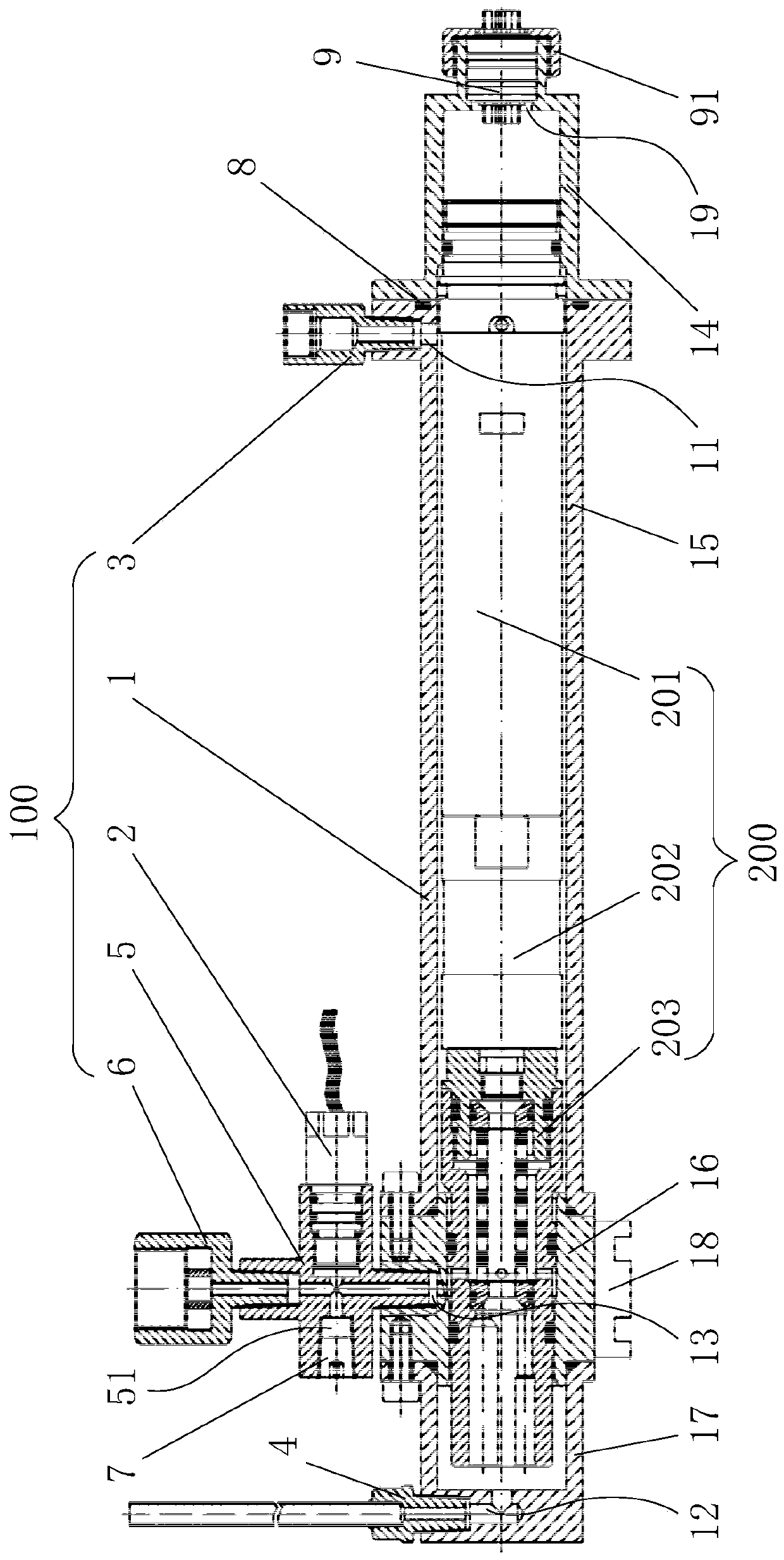
[0027] In the description of this application, it is to be understood that the terms "center", "upper", "lower", "front", "rear", "left", "right", "vertical", "horizontal", The orientation or positional relationship indicated by "top", "bottom", "inner", "outer", "axial", "radial" and "circumferential" are based on the orientation or positional relationship shown in the drawings, only It is for the convenience of describing the application and simplifying the description, rather than indicating or implying that the device or element referred to must have a specific orientati...


PUM


Abstract

The invention discloses a testing device of a rotary guiding tool hydraulic control system. The rotary guiding tool hydraulic control system comprises a motor assembly, a plunger pump assembly and a control valve assembly. The testing device comprises a testing barrel, a pressure detection assembly and a control assembly, wherein an accommodating chamber is formed in the testing barrel; the accommodating chamber is used for fixedly mounting the hydraulic control system; an oil inlet, an oil return hole and a pressure testing hole which communicate with the accommodating chamber are further formed in the testing barrel; the pressure testing hole communicates with a pressure output hole of the hydraulic control system; the pressure detection assembly is arranged at the pressure testing holeand is used for detecting output pressure of the hydraulic control system; and the control assembly is electrically connected with the motor assembly, and detects and controls rotation speed of the motor assembly. According to the testing device, performance index testing can be carried out on the entire hydraulic control system, and a testing result is similar to the real working condition and isaccurate and reliable; and besides, the structure is simple, utilization is convenient, the testing device is time-saving and effort-saving, testing efficiency is high, and a testing means is provided for real market application of the hydraulic control system.

Description

technical field [0001] The application belongs to the technical field of petroleum drilling, and in particular relates to a test device for a hydraulic control system of a rotary steerable tool. Background technique [0002] Rotary steerable drilling technology is to conduct steerable drilling under the condition of full rotation of the drill string. A controllable bias stabilizer or a rotary steerable tool that can control the lateral force (steering force) of the drill bit is installed above the drill bit, and is equipped with a complete rotary steerable Drilling control system, a technology that can regulate the trajectory of the wellbore when the drill string is rotating and drilling. When using rotary steerable drilling technology for drilling operations, three-dimensional wellbore trajectory control can be realized without frequent tripping, and it has the advantages of smoother wellbore trajectory and greater extension distance, which is very important for ensuring th...

Claims


Application Information

Patent Timeline
Patent Type & Authority Patents(China)
IPC IPC(8): F15B19/00
Inventor 刘庆波底青云王自力陈文轩杨永友杜建生何新振
Owner INST OF GEOLOGY & GEOPHYSICS CHINESE ACAD OF SCI
Why Eureka
Try Eureka