Eccentric wheel synchronous rotating driving mechanism

A technology of synchronous rotation and driving mechanism, which is applied in the direction of electromechanical devices, mechanical equipment, electric components, etc., can solve the problems of inability to complete the rotation of multiple parts at the same deflection angle, increase equipment costs, and low synchronization rate, etc., to reduce Effects of equipment cost, improvement of deflection efficiency, and improvement of synchronization rate

Pending Publication Date: 2019-06-07
SUZHOU RS TECH
View PDF13 Cites 2 Cited by
  • Summary
  • Abstract
  • Description
  • Claims
  • Application Information

AI Technical Summary

Problems solved by technology

[0002] On non-standard automated assembly lines, it is often necessary to use a rotary drive mechanism to deflect the parts to be assembled in the horizontal plane, and then adjust the horizontal posture of the parts in real time to improve assembly accuracy. The existing rotary drive mechanism There are the following problems: most of the existing rotary drive mechanisms are driven by rotary motors. When multiple parts need to be synchronously rotated and driven, multiple rotary motors are required, which not only increases the cost of equipment, but also has a low synchronization rate. , it is impossible to meet the requirement of rotating multiple components at the same deflection angle

Method used


Image

  • Eccentric wheel synchronous rotating driving mechanism
  • Eccentric wheel synchronous rotating driving mechanism
  • Eccentric wheel synchronous rotating driving mechanism

Examples


Embodiment Construction

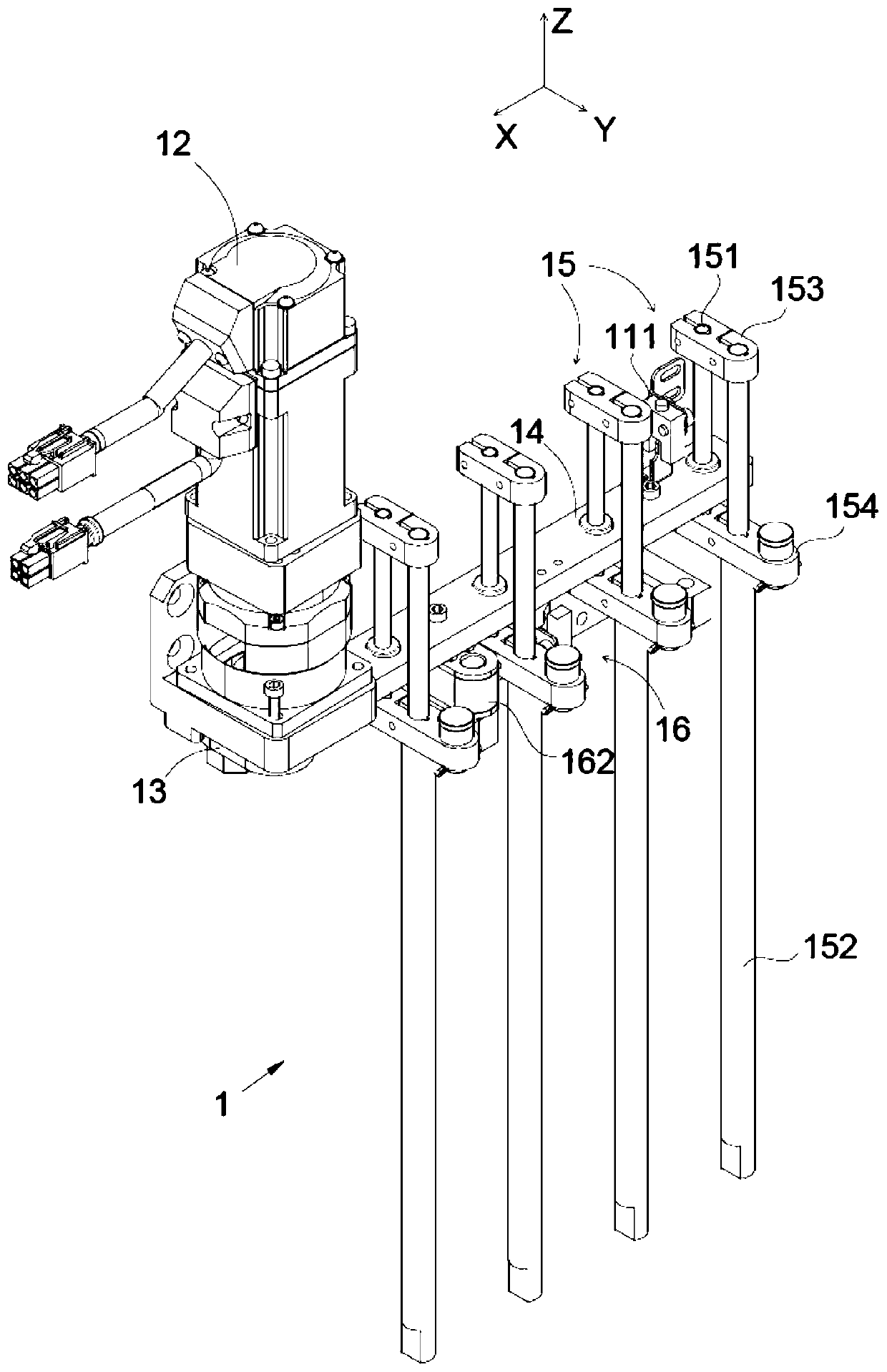
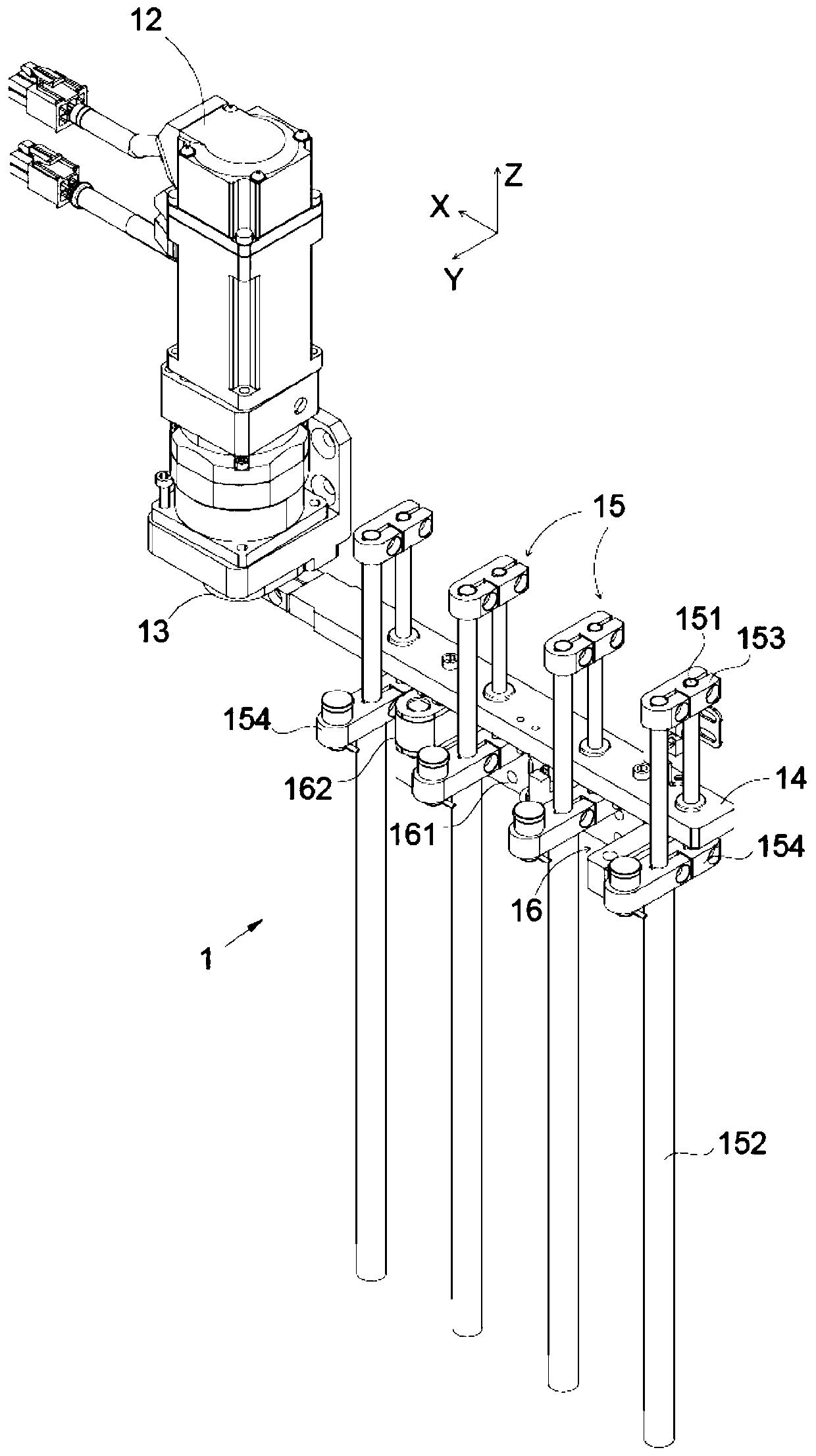
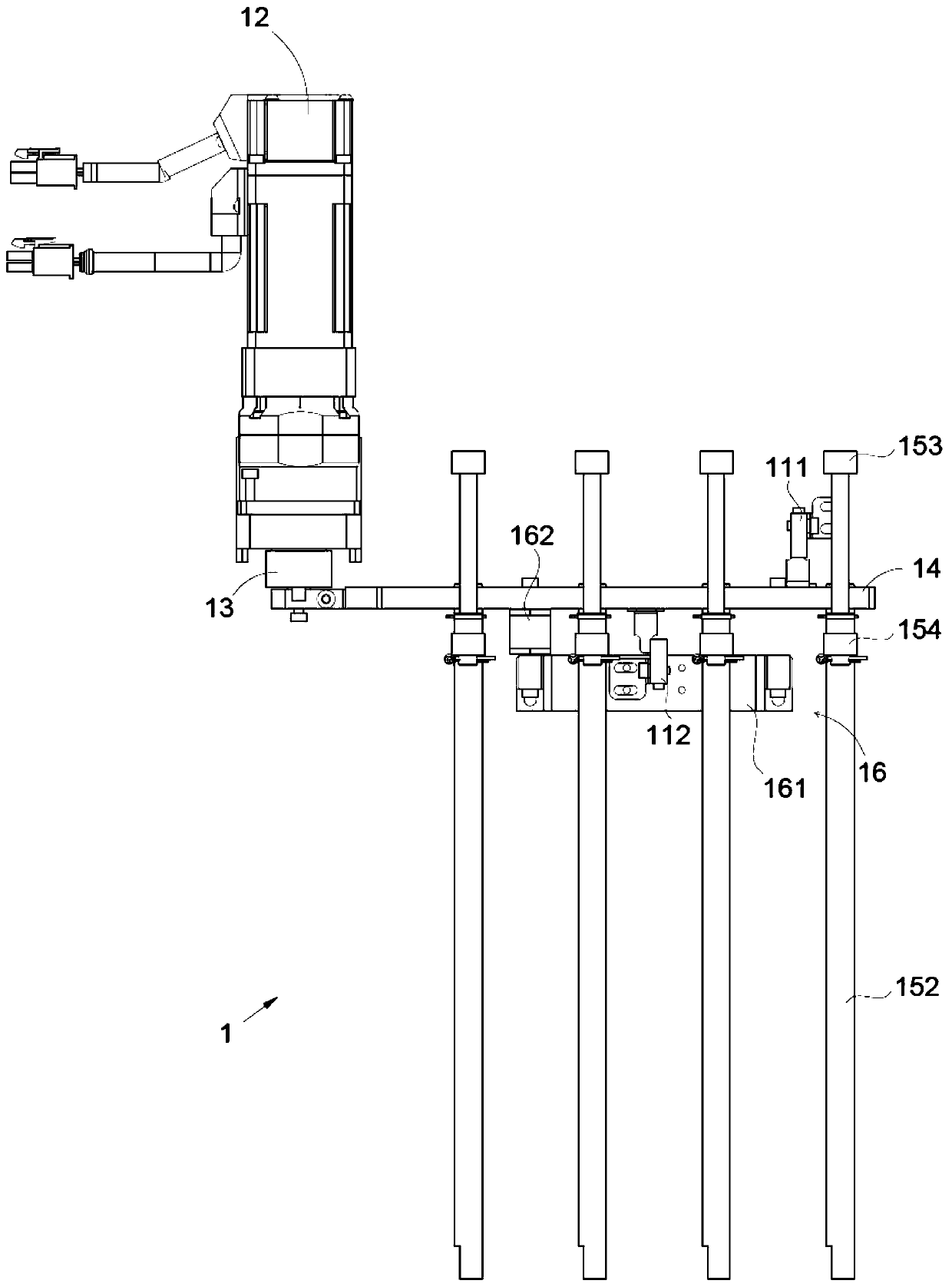
[0027] The present invention will be further described in detail below in conjunction with the accompanying drawings, and the aforementioned and other objects, features, aspects and advantages of the present invention will become more apparent, so that those skilled in the art can implement them with reference to the description. In the drawings, the shapes and dimensions may be exaggerated for clarity, and the same reference numerals will be used throughout to designate the same or like parts. In the following description, terms such as center, thickness, height, length, front, back, rear, left, right, top, bottom, upper, lower, etc. are based on the orientation or positional relationship shown in the drawings. In particular, "height" corresponds to the dimension from top to bottom, "width" corresponds to the dimension from left to right, and "depth" corresponds to the dimension from front to back. These relative terms are for convenience of description and are generally not ...


PUM


Abstract

The invention discloses an eccentric wheel synchronous rotating driving mechanism which comprises an eccentric wheel, a transmission plate and rotating assemblies. The transmission plate is eccentrically and rotationally connected with the eccentric wheel. The rotating assemblies are connected with the transmission plate in a rotating and sliding manner, and at least two rotating assemblies are arranged. Each rotating assembly comprises a rotating shaft connected with the transmission plate in a rotating and sliding manner, and a lifting shaft, wherein the rotating shaft and the lifting shaftare arranged in parallel in a spaced manner, and a connecting rod is fixedly connected between the rotating shaft and the lifting shaft. By means of the eccentric wheel synchronous rotating driving mechanism, a traditional rotating motor driving manner is abandoned, an eccentric transmission manner is adopted, only one power source is needed, the equipment cost is reduced, in addition, the synchronous rate is increased, the installation space is reduced, real-time synchronous deflection can be conducted on multiple parts, and the deflection efficiency is improved.

Description

technical field [0001] The invention relates to the field of non-standard automation, in particular to an eccentric wheel synchronous rotation drive mechanism. Background technique [0002] On non-standard automated assembly lines, it is often necessary to use a rotary drive mechanism to deflect the parts to be assembled in the horizontal plane, and then adjust the horizontal posture of the parts in real time to improve assembly accuracy. The existing rotary drive mechanism There are the following problems: most of the existing rotary drive mechanisms are driven by rotary motors. When multiple parts need to be synchronously rotated and driven, multiple rotary motors are required, which not only increases the cost of equipment, but also has a low synchronization rate. , it is impossible to fulfill the requirement of multiple components rotating at the same deflection angle. In view of this, it is necessary to develop an eccentric wheel synchronous rotation drive mechanism to...

Claims


Application Information

Patent Timeline
Patent Type & Authority Applications(China)
IPC IPC(8): F16H21/18F16H21/04H02K7/06
CPCH02K7/06F16H21/04F16H21/18
Inventor 吴加富缪磊蒋玉斌林杰
Owner SUZHOU RS TECH
Why Eureka
Try Eureka