Steam heat exchanger capable of evenly distributing flow

A technology of uniform distribution and heat exchangers, applied in the direction of heat exchanger types, indirect heat exchangers, heat exchange equipment, etc., to achieve stable flow, avoid uneven segmentation, and promote smooth flow.

Active Publication Date: 2019-06-07
国网山东省电力公司聊城供电公司 +2
View PDF7 Cites 2 Cited by
  • Summary
  • Abstract
  • Description
  • Claims
  • Application Information

AI Technical Summary

Problems solved by technology

[0005] The present invention provides a new heat exchange tube heat exchanger, thereby solving the technical problems arising above

Method used


Image

  • Steam heat exchanger capable of evenly distributing flow
  • Steam heat exchanger capable of evenly distributing flow
  • Steam heat exchanger capable of evenly distributing flow

Examples


Embodiment Construction

[0040] The specific embodiments of the present invention will be described in detail below in conjunction with the accompanying drawings.

[0041] In this article, if there is no special explanation, when it comes to formulas, " / " means division, and "×" and "*" mean multiplication.

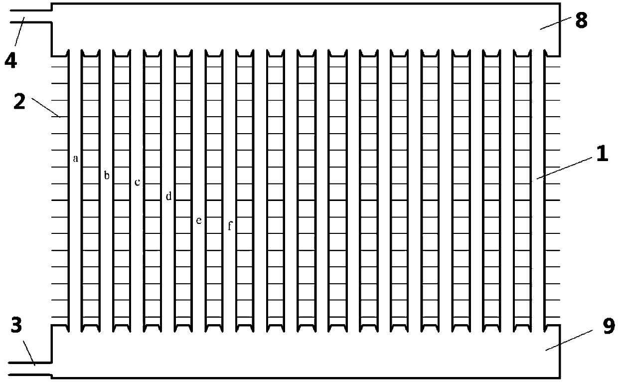
[0042] a heat exchanger such as figure 1 As shown, the heat exchanger includes an upper header 8 and a lower header 9 and a heat exchange tube 1 arranged between the upper and lower headers 8 and 9 . Preferably, fins 2 are arranged outside the heat exchange tubes. The heat exchanger may be a steam heat exchanger, and the steam flows in the heat exchange tube 1 as a heat source. To heat the cold source around the heat exchange tube, such as water. This results in the formation of a vapor-liquid two-phase flow in the heat exchange tube 1 .

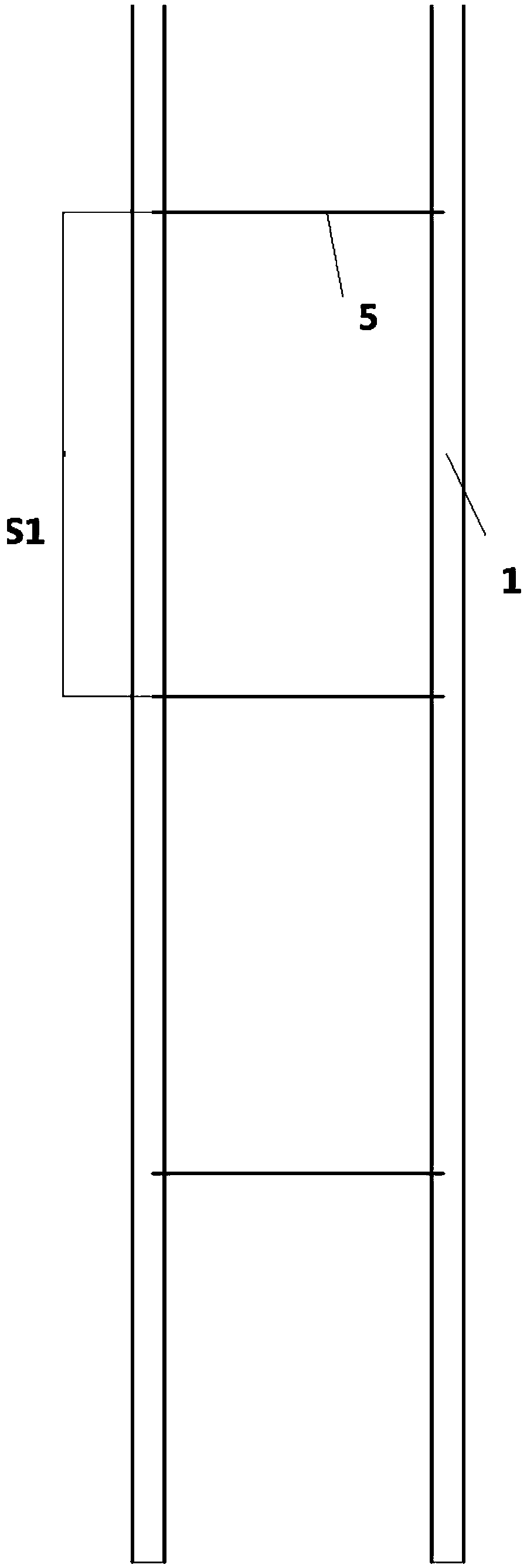
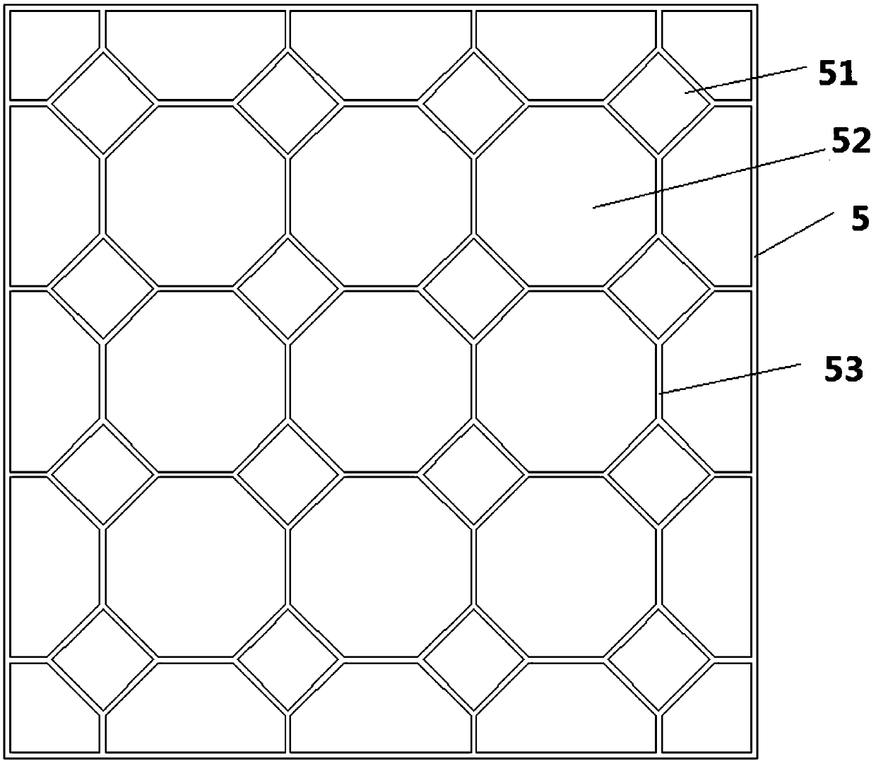
[0043] Such as Figures 2 to 3 As shown, an annular partition device 5 is provided inside the heat exchange tube 1 . The structure of the annular spacer ...


PUM


Abstract

The invention provides a steam heat exchanger capable of evenly distributing flow. The steam heat exchanger comprises an upper collecting box, a lower collecting box and heat exchange pipes arranged between the upper collecting box and the lower collecting box. A heat source in the heat exchange pipe is steam. The heat exchanger comprises an inlet pipe. The inlet pipe is arranged on the lower collecting box. Partition devices are arranged in the heat exchange pipes. Each partition device is of a sheet structure and is composed of square through holes and regular octagonal through holes. The side lengths of the square through holes in the different heat exchange pipes are different, and the longer the distances away from the inlet pipe are, the larger the side lengths of the square throughholes are. By changing the side lengths of the square through holes along with the distances away from the inlet pipe, fluid is made to flow into the heat exchange pipes which are small in flowing resistance and long in distances away from the inlet pipe, and therefore the fluid can be evenly distributed in the heat exchange pipes, the heat exchange efficiency is improved, and the service life isprolonged.

Description

technical field [0001] The invention relates to a heat exchanger, in particular to a shell-and-tube heat exchanger. Background technique [0002] Immersed shell and tube heat exchangers have been widely used in recent years for automotive air conditioning units as well as residential or commercial air conditioning heat exchangers. A plurality of small channels are arranged inside the heat exchange tube, and the heat exchange fluid flows through the plurality of channels in the heat exchange tube during use. Because the heat exchange tube has a large heat exchange area, the heat exchange effect can be greatly improved. [0003] In the prior art, there is a problem of uneven flow distribution caused by the distance between the heat exchange tube and the inlet tube. For example, the closer the distance to the inlet tube, the more fluid flow in the heat exchange tube; Fluid flow is less. In the prior art, the flow distribution or pressure distribution components are installed...

Claims


Application Information

Patent Timeline
Patent Type & Authority Applications(China)
IPC IPC(8): F28D7/16F28F1/00
Inventor 张国庆焦敏许吉凯张海静魏晓蔚靳印涵鞠文杰许冬琪汪东军牛蔚然牟强魏姗姗张冠敏张毅邱燕王效嘉江程李言伟
Owner 国网山东省电力公司聊城供电公司
Why Eureka
Try Eureka