
A Correction Method of Radar Direction Finding Relative Systematic Error

A system error and radar direction finding technology, applied to radio wave measurement systems, measurement devices, instruments, etc., can solve problems such as increased relative error, little correlation with real track, and difficult to grasp

Active Publication Date: 2020-11-20
STRATEGIC EARLY WARNING RES INST OF THE PEOPLES LIBERATION ARMY AIR FORCE RES INST
View PDF4 Cites 0 Cited by
  • Summary
  • Abstract
  • Description
  • Claims
  • Application Information

AI Technical Summary

Problems solved by technology

Traditional data calibration methods attempt to estimate the absolute systematic error present in a radar measurement from such measurement data
However, the simulation test shows that the target track after system error correction depends on the relative positions of all the original measurement tracks of the single radar involved in the calculation, and has little correlation with the real track
In practical engineering applications, the estimated results of the systematic error of radar A will be different due to the measurement data of radar B or radar C. If it is agreed that the systematic error calculated by the data of A and B is the absolute systematic error of radar A, Then there may be a contradiction between the reduction of the relative error of A and B and the increase of the relative error of A and C, so the idea of ​​finding the absolute system error is difficult to grasp in engineering practice

Method used

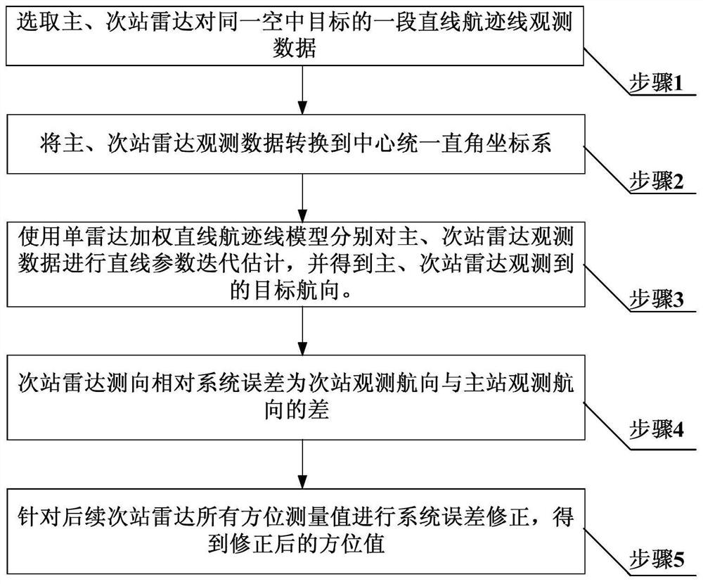
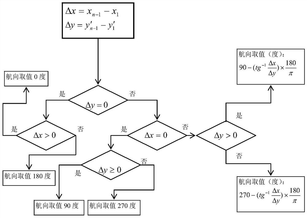
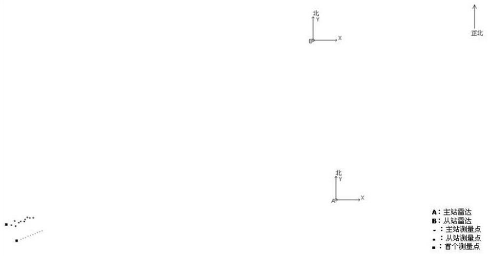

Image

  • A Correction Method of Radar Direction Finding Relative Systematic Error
  • A Correction Method of Radar Direction Finding Relative Systematic Error
  • A Correction Method of Radar Direction Finding Relative Systematic Error

Examples


Embodiment 1

[0220] The radar direction-finding relative system error correction method provided in this embodiment is used in the early data preprocessing process of multi-radar detection system data fusion.

[0221] The correction method includes the steps of:

[0222] Step 1: Select the observation data of a straight track of the same air target by the primary and secondary station radars, see Table 2 and Table 3.

[0223] Table 1: Basic parameters

[0224]

[0225]

[0226] Table 2: Radar observation data of the main station

[0227] serial number time t Azimuth θ (degrees) Distance ρ(km) 1 10:30:05 262.7 451.7 2 10:30:22 262.9 445.7 3 10:30:33 263.0 442.3 4 10:30:43 263.1 438.9 5 10:30:53 263.3 435.4 6 10:31:03 263.4 432.0 7 10:31:14 263.5 428.5 8 10:31:24 263.6 425.1 9 10:31:34 263.8 421.6 10 10:31:44 263.9 418.2 11 10:31:54 264.0 414.9

[0228] Table 3: Secondary station radar ob...


PUM


Abstract

The invention belongs to the technical field of multi-radar data fusion, and specifically relates to a radar direction finding relative system error correction method. In order to accurately estimateand correct direction finding relative system errors existing in radar measurement, reduce the splitting degree of multi-radar observation tracks and meet the requirements of correlation consistency and accuracy, the invention comprises the steps of selecting a set of observation data of primary and secondary station radar for a certain typical route target, carrying out central unified rectangular coordinate transformation on the observation data, then proposing and adopting the means such as a single radar weighted linear track line model to carry out iterative estimation on radar observation track line parameters, determining the observation headings of the primary and secondary station radar by adopting a point taking orientation method, finally acquiring a direction finding relative system error of the secondary station radar relative to the primary station radar, and correcting the direction value of the secondary station radar in subsequent measurement according to the estimation result. The method is scientific and reasonable in scheme implementation step and ideal in track correction effect. The method is very low in time complexity and space complexity and very strong inoperability and practicability.

Description

technical field [0001] The invention belongs to the technical field of multi-radar data fusion, and in particular relates to a radar direction finding relative system error correction method. Background technique [0002] The relative systematic error of radar direction finding refers to the systematic error relative to the designated reference system when the radar measures the azimuth of the target, including the direction finding error in the dynamic measurement of the radar and the fixed error when the radar site is calibrated to the north. One of the main components of radar network intelligence system error, sometimes called true north error. [0003] After multi-radar networking, the calibration error of different radar positions, the inherent deviation caused by the position environment to the radar measurement, and the systematic error in the measurement that cannot be eliminated in the design of the radar itself make each point on the track of each single radar Af...

Claims


Application Information

Patent Timeline
Patent Type & Authority Patents(China)
IPC IPC(8): G01S13/58G01S7/40
Inventor 王建涛高效方维华董光波金宏斌陈钢张金泽张卫荣冯亚军张辉祝琳钟恢扶田科钰李静
Owner STRATEGIC EARLY WARNING RES INST OF THE PEOPLES LIBERATION ARMY AIR FORCE RES INST
Learn More