
Soft tissue injury simulation testing device

A soft tissue injury and simulation test technology, applied in the field of medical simulation test, can solve the problems of lack of accurate grasp of treatment parts, lack of dynamic and fine numerical analysis methods for tissue structure composition analysis, blind selection of diagnosis and treatment parts, etc.

Active Publication Date: 2019-06-07
HUAZHONG UNIV OF SCI & TECH
View PDF16 Cites 0 Cited by
  • Summary
  • Abstract
  • Description
  • Claims
  • Application Information

AI Technical Summary

Problems solved by technology

[0002] At present, the theoretical explanations for the use of acupuncture and needle-knife minimally invasive blindness treatment techniques in the diagnosis and treatment of human soft tissue injury pain are seriously insufficient, especially the selection of diagnosis and treatment sites is blind, some are near the joints, some are in the muscles, and for different Many patients have their own opinions on the treatment effect, which leads many doctors to lack accurate grasp of the treatment site when using acupuncture and acupotomy.
The key to this problem is the lack of understanding of the material composition and motion performance of soft tissue, and the lack of a clear tissue structure composition analysis and dynamic fine numerical analysis method for the mechanical control model and diagnosis and treatment mechanism for the understanding of soft tissue injury pain.

Method used


Image

  • Soft tissue injury simulation testing device
  • Soft tissue injury simulation testing device
  • Soft tissue injury simulation testing device

Examples


Embodiment Construction

[0031] In order to make the object, technical solution and advantages of the present invention clearer, the present invention will be further described in detail below in conjunction with the accompanying drawings and embodiments. It should be understood that the specific embodiments described here are only used to explain the present invention, not to limit the present invention. In addition, the technical features involved in the various embodiments of the present invention described below can be combined with each other as long as they do not constitute a conflict with each other.

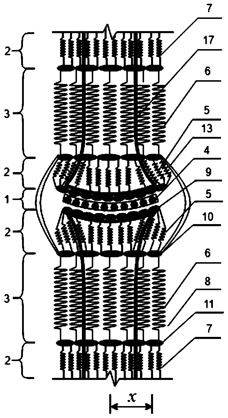
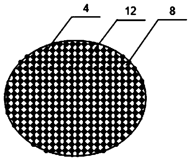
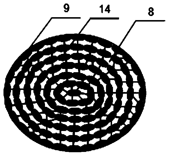
[0032] figure 1 It is a schematic diagram of the soft tissue structure of the embodiment of the soft tissue injury simulation test device of the present invention. The device includes: a joint cavity simulation piece, a soft tissue simulation structure 1 , a toughness simulation structure 2 , a muscle elasticity simulation structure 3 , a ligament 13 and an active viscous body fluid 8 .

[003...


PUM


Abstract

The invention discloses a soft tissue injury simulation testing device. According to the structure of the soft tissue injury simulation testing device, slippage of a soft tissue simulation structure represents friction between joints, and unevenness of the surface represents unevenness of the cartilage surface; a first toughness simulation structure and a second toughness simulation structure arelocated on the two sides of the soft tissue simulation structure respectively and used for simulating connection portions of the joints and the muscle tissue; a first muscle elastic simulation structure and a second muscle elastic simulation structure are located on the other side of the first toughness simulation structure and the other side of the second toughness simulation structure respectively and used for simulating the muscle tissue; the two ends of ligaments are connected with the first and second toughness simulation structures respectively and used for preventing the first and second toughness simulation structures from deforming excessively; an active viscous body fluid is used for simulating the synovial fluid and the inter-tissue fluid. By the adoption of the soft tissue injury simulation testing device, the soft tissue injury condition can be simulated, then, the essential causes of soft tissue injury pain can be elucidated in mechanism by analyzing tissue structure components and mechanical mechanisms of all the components, and thus a testing platform can be provided for acupuncture and acupotomology blind diagnosis and treatment.

Description

technical field [0001] The invention belongs to the technical field of medical simulation tests, and in particular relates to a soft tissue injury simulation test device, which is used to simulate damaged soft tissues, on which a formulated diagnosis and treatment plan is applied for test evaluation. Background technique [0002] At present, the theoretical explanations for the use of acupuncture and needle-knife minimally invasive blindness treatment techniques in the diagnosis and treatment of human soft tissue injury pain are seriously insufficient, especially the selection of diagnosis and treatment sites is blind, some are near the joints, some are in the muscles, and for different Many patients have their own opinions on the treatment effect, which leads to the lack of accurate grasp of the treatment site when many doctors use acupuncture and acupotomy. The key to this problem is the lack of understanding of the material composition and motion performance of soft tissu...

Claims


Application Information

Patent Timeline
Patent Type & Authority Applications(China)
IPC IPC(8): G09B23/28
Inventor 桑永朋高常鑫
Owner HUAZHONG UNIV OF SCI & TECH
Learn More