
Cylindrical shaft sleeve fixture

A cylindrical and shaft sleeve technology is applied in the field of machining to achieve the effects of simple connection relationship, easy operation and low production cost

Inactive Publication Date: 2019-06-11
新昌县瑞宏自动化设备有限公司
View PDF0 Cites 0 Cited by
  • Summary
  • Abstract
  • Description
  • Claims
  • Application Information

AI Technical Summary

Problems solved by technology

[0002] In the existing mechanical processing technology, for the processing of shaft sleeve workpieces, more general fixtures are used for processing, but the process of workpieces cannot meet the existing processing requirements only by relying on general fixtures and shaft sleeves for assistance. Therefore, how to design the structure of the shaft sleeve type fixture can not only meet the needs of fixing different types of shaft sleeves, but also make corresponding displacement adjustments, so as to reduce the production cost and difficulty of use of the fixture, which has become a technical problem faced by the current industry.

Method used


Image

  • Cylindrical shaft sleeve fixture
  • Cylindrical shaft sleeve fixture
  • Cylindrical shaft sleeve fixture

Examples


Embodiment Construction

[0022] It should be noted that, in the case of no conflict, the embodiments of the present invention and the features in the embodiments can be combined with each other.

[0023] In describing the present invention, it should be understood that the terms "center", "longitudinal", "transverse", "upper", "lower", "front", "rear", "left", "right", " The orientations or positional relationships indicated by "vertical", "horizontal", "top", "bottom", "inner" and "outer" are based on the orientations or positional relationships shown in the drawings, and are only for the convenience of describing the present invention and Simplified descriptions, rather than indicating or implying that the device or element referred to must have a particular orientation, be constructed and operate in a particular orientation, and thus should not be construed as limiting the invention. In addition, the terms "first", "second", etc. are used for descriptive purposes only, and should not be interpreted...


PUM


Abstract

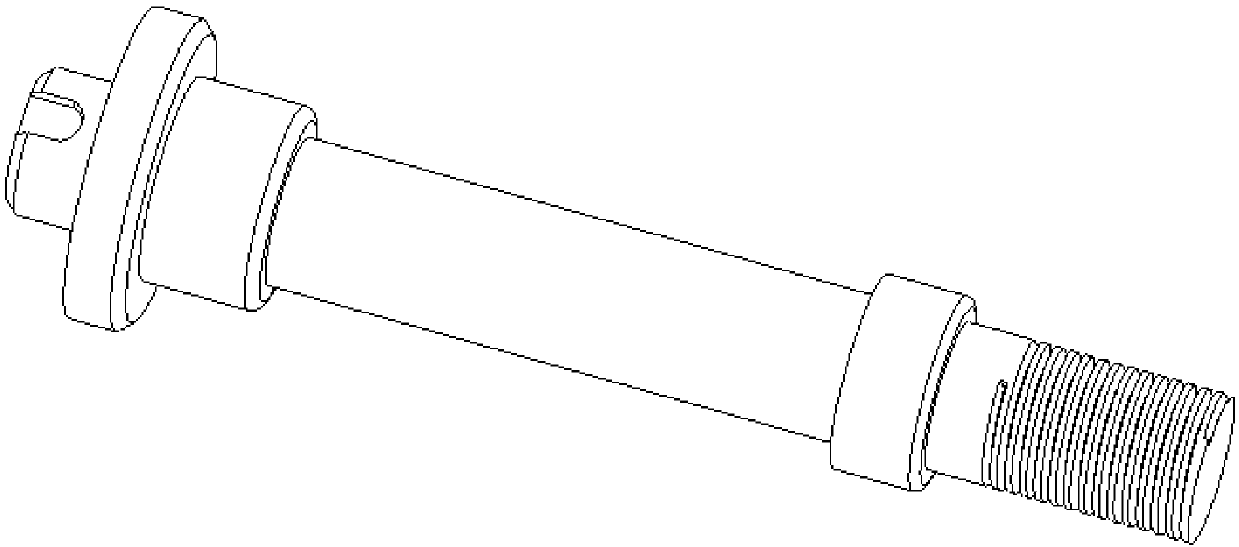
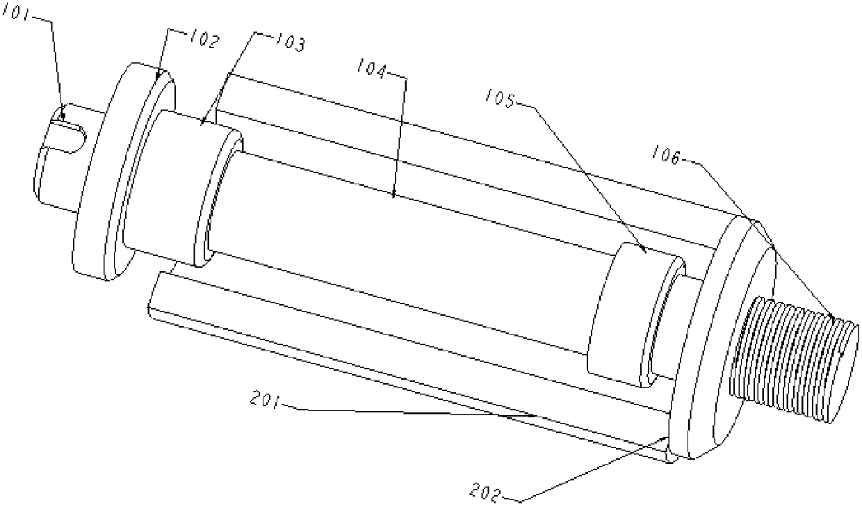
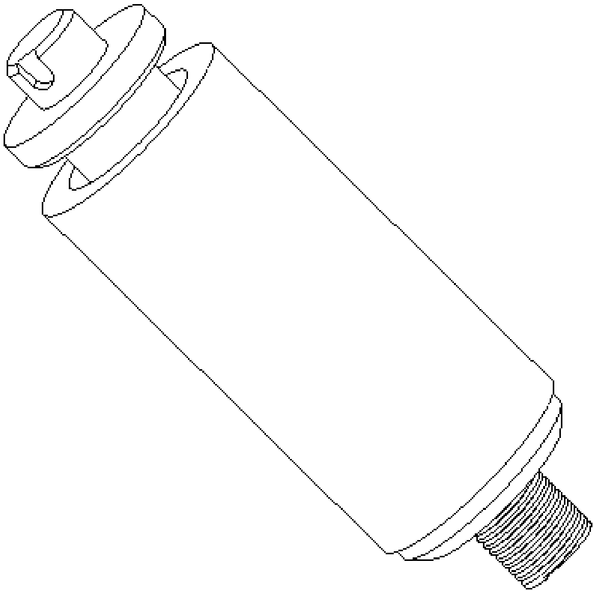
The invention provides a cylindrical shaft sleeve fixture. The cylindrical shaft sleeve fixture comprises a clamping rod main body and a sleeve main body; the clamping rod main body is provided with akey groove, an upper clamping plate, an upper shaft column, a lower shaft column and a thread for fixing sleeve workpieces; the outer surfaces of the workpieces are clamped by the sleeve main body; the sleeve main body comprises a sleeve, and a base plate arranged at the lower end of the sleeve; and the base plate is provided with a thread hole matched with the thread of the clamping rod main body. In the cylindrical shaft sleeve fixture, the clamping rod main body and the sleeve form a fixture main body; and the cylindrical shaft sleeve fixture can meet clamping of a straight cylinder and astep cylinder, and is simple in structure, low in production cost and simple and convenient to use.

Description

technical field [0001] The invention belongs to the field of mechanical processing, and in particular relates to a cylindrical shaft sleeve fixture. Background technique [0002] In the existing mechanical processing technology, for the processing of shaft sleeve workpieces, more general fixtures are used for processing, but the process of workpieces cannot meet the existing processing requirements only by relying on general fixtures and shaft sleeves for assistance. Therefore, how to design the structure of the shaft sleeve fixture, which can not only meet the fixation of different types of shaft sleeves, but also adjust the corresponding displacement, reduce the manufacturing cost and difficulty of use of the fixture, has become a technical problem faced by the current industry. Contents of the invention [0003] In view of this, the present invention aims to propose a cylindrical shaft sleeve type clamp, the structure of the clamp body is composed of the clamp rod body ...

Claims


Application Information

Patent Timeline
Patent Type & Authority Applications(China)
IPC IPC(8): B23Q3/00
Inventor 丁万里
Owner 新昌县瑞宏自动化设备有限公司
Learn More