Vehicle air condition controller

A vehicle air conditioner and controller technology, which is applied to vehicle components, air handling equipment, heating/cooling equipment, etc., and can solve the problems of independent torque control of unfavorable gears and independent torque control.

Active Publication Date: 2019-06-11
NINGBO FUERDA SMARTECH CO LTD
View PDF13 Cites 0 Cited by
  • Summary
  • Abstract
  • Description
  • Claims
  • Application Information

AI Technical Summary

Problems solved by technology

background technology such as figure 1 As shown, the two elastic components 001 and 002 are in contact with the grooves on the same surface 003, the torque of the gear position is mainly determined by the elastic coefficient of the elastic components 001 and 002 and the limit groove, the torque of the two gears is related to the two The elast

Method used


Image

  • Vehicle air condition controller
  • Vehicle air condition controller
  • Vehicle air condition controller

Examples


specific Embodiment approach 1

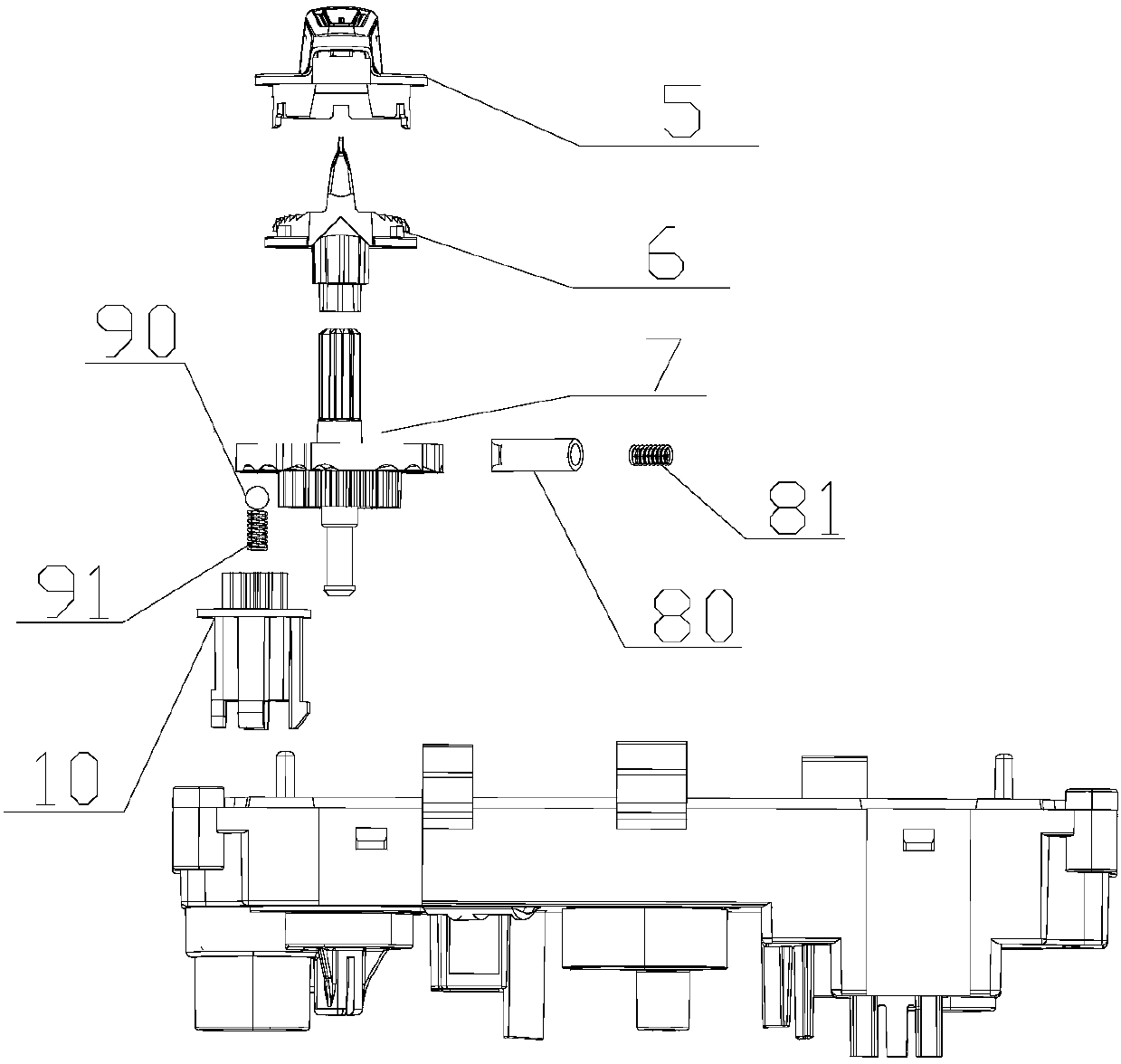
[0037] see in conjunction Figure 9 with Figure 10 , Figure 9 is a front view structural schematic diagram of the first specific embodiment of the transmission member, Figure 10 It is a schematic diagram of the isometric side structure of the first specific embodiment of the transmission member. A circuit board is installed between the light guide member 6 and the transmission member 7 , and an assembly hole is opened on the circuit board, and the transmission shaft 70 of the transmission member 7 passes through the assembly hole and is socketed with the mode knob 2 . The transmission member 7 mainly includes a transmission shaft 70 , a limiting portion 71 , a first disk portion 72 , a gear portion 73 and a connecting rod 74 , and a buckle 75 is provided at the end of the connecting portion 74 . The transmission shaft 70 is socketed with the casing part 63 through the assembly hole, and the transmission shaft 70 is provided with a first guide rib along the axial directio...

specific Embodiment approach 2

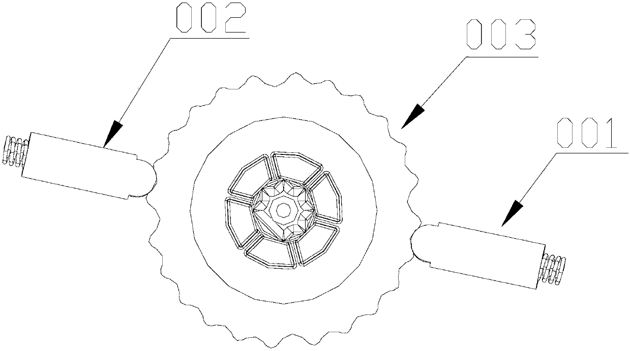
[0046] see in conjunction Figure 16 Figure 17 , Figure 16 It is a schematic structural diagram of the front view of the second specific embodiment of the transmission member, Figure 17 It is a schematic diagram of the isometric structure of the second specific embodiment of the transmission member. The transmission member 7 mainly includes a transmission shaft 70 , a limiting portion 71 , a first disk portion 72 , a second disk portion 78 , a gear portion 73 and a connecting rod 74 , and a buckle 75 is provided at the end of the connecting portion 74 . Both the first disk portion 72 and the second disk portion 78 are centered on the transmission shaft 70, and the first disk portion 72 and the second disk portion 78 have a certain thickness, and the side walls of the first disk portion 72 The outer periphery is provided with a first groove 76, and the outer periphery of the side wall of the second disk part 78 is provided with a second groove 77. The first groove 76 exte...

specific Embodiment approach 3

[0051] see in conjunction Figure 19 with Figure 20 , Figure 19 is a front view structural schematic diagram of the third specific embodiment of the transmission member, Figure 20 It is a structural schematic diagram of the isometric side rear view of the third specific embodiment of the transmission member. The transmission member 7 mainly includes a transmission shaft 70 , a limiting portion 71 , a first disk portion 72 , a second disk portion 78 , a gear portion 73 and a connecting rod 74 , and a buckle 75 is provided at the end of the connecting portion 74 . The disk surface of the first disk portion 72 is parallel to the disk surface of the second disk portion 78 and both disk surfaces are centered on the drive shaft 70, the first disk portion 72 and the second disk portion 78 are both It has a certain thickness. The disk surface of the first disk part 72 facing the rear cover 1 is the lower surface, and the lower surface of the first disk part 72 is provided with a...


PUM


Abstract

The invention discloses a vehicle air condition controller which comprises a transmission structure. The transmission structure includes a transmission member and elastic assemblies, wherein the elastic assemblies include a first elastic assembly and a second elastic assembly, the transmission member includes a first surface and a second surface, the first elastic assembly is in contact with the first surface of the transmission member, and the second elastic assembly is in contact with the second surface of the transmission member. The action of the first elastic assembly on the transmissionmember is located on the first surface, the action of the second elastic assembly on the transmission member is located on the second surface, the first surface and the second surface are different surfaces, and thus the torque generated between the first elastic assembly and the transmission member is independent from the torque generated between the second elastic assembly and the transmission member to be conducive to separate control over different torques.

Description

【Technical field】 [0001] The invention relates to the field of automobiles, in particular to a vehicle air conditioner controller. 【Background technique】 [0002] The car air-conditioning controller can realize the adjustment of parameters such as the mode, air volume and temperature of the car air-conditioning by manually operating the knob. The knob can also be used for gear adjustment in the air-conditioning mode, and the operating feel of the gear can be realized by setting the transmission member and the elastic component. The transmission part includes a disc part, and different types of grooves are provided along the outer peripheral surface of the side wall of the disc part. The elastic component contacts the groove along the outer peripheral surface of the side wall of the disc part, and the torque generated by the elastic component entering and leaving different grooves Different, so as to realize the operation feel of different gears. Background technology such ...

Claims


Application Information

Patent Timeline
IPC IPC(8): B60H1/00
Inventor 不公告发明人
Owner NINGBO FUERDA SMARTECH CO LTD
Why Eureka
Try Eureka