Vertical air conditioner indoor unit

A technology for vertical air conditioners and indoor units, which is applied in air conditioning systems, heating methods, space heating and ventilation, etc. It can solve the problems of complex molds, inconvenient processing, occupying air conditioning space and air ducts, etc., and achieve simple molds, convenient production, The effect of improving air supply performance

Active Publication Date: 2019-05-31
QINGDAO HAIER AIR CONDITIONER GENERAL CORP LTD
View PDF10 Cites 0 Cited by
  • Summary
  • Abstract
  • Description
  • Claims
  • Application Information

AI Technical Summary

Problems solved by technology

[0004] The above processing method has the following disadvantages: First, the realization of the additional air processing function is dependent on the original structure and operation of the air conditioner, and cannot be controlled independently
Second, once the air conditioner is shipped from the factory, the additional air treatment function has been determined, and the user cannot change it, making it difficult to meet individual needs
Third, due to the increase of additional air processing modules, the original space and air duct of the air conditioner are occupied, which affects the original normal air conditioning performance of the air conditioner; in order to realize the coordination and matching of the normal air conditioning and additional air conditioning of the air conditioner, a lot of research and development is required The design of the air-conditioning structure and electric control at low cost
At present, the front volute and the rear volute forming the air duct of the cross-flow fan are all of one-piece structure, and the mold is complicated, which is not easy to process
Moreover, due to the one-piece structure, if only the front volute profile or the rear volute profile is to be modified to meet the air supply requirements, the overall mold corresponding to the two volutes must be changed at the same time, which is costly and difficult

Method used


Image

  • Vertical air conditioner indoor unit
  • Vertical air conditioner indoor unit
  • Vertical air conditioner indoor unit

Examples


Embodiment Construction

[0030] In order to make the object, technical solution and advantages of the present invention clearer, the present invention will be further described in detail below in conjunction with the accompanying drawings and embodiments.

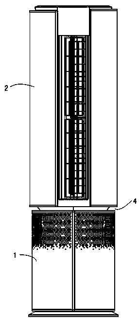
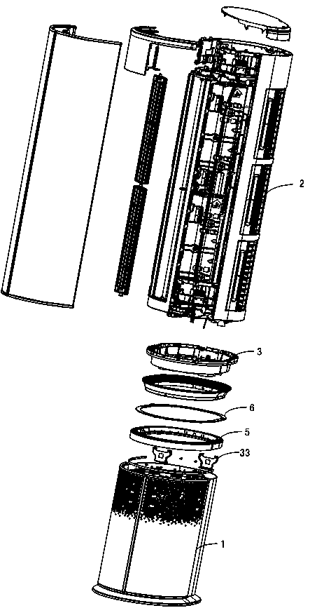
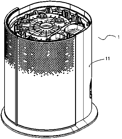
[0031] See Figure 1 to Figure 5 An embodiment of the vertical air conditioner indoor unit of the present invention is shown, wherein, figure 1 It is a perspective view of the vertical air conditioner indoor unit of this embodiment, figure 2 yes figure 1 structure breakdown diagram, image 3 and Figure 4 Respectively are the three-dimensional view and the structural exploded view of the base in the embodiment, Figure 5 is a perspective view of the connector in the embodiment.

[0032] Such as Figure 1 to Figure 5 As shown, the vertical air conditioner indoor unit of this embodiment includes a cylindrical base 1 and an air conditioner body 2 as a whole, and the base 1 and the air conditioner body 2 are detachably assembled. But it is not ...


PUM


Abstract

The invention discloses a vertical air conditioner indoor unit. The indoor unit comprises an air conditioner main body wherein the air conditioner main body comprises a front volute and a back volute which form an air duct and a cross flow fan is formed in the air duct; a base which is detachably assembled with the air conditioner main body, wherein the base comprises a base main body. The base main body comprises an assembly part. A main body air inlet and a main body air outlet are formed on the base main body. A hollow cavity is formed in the base main body. An air fan and an air treatment module are formed in the hollow cavity. The front volute and the back volute are detachably connected with each other, so that the air duct of the cross flow fan is formed. After the base and the air conditioner main body are assembled together, the additional air treatment function which is performed by the base is independent with the air conditioner main body. The structure of the original air conditioner main body is not affected, and the additional air treatment function does not depend on the operation of the original air conditioner main body and can independently run.

Description

technical field [0001] The invention belongs to the technical field of air conditioning, and in particular relates to a vertical air conditioner indoor unit. Background technique [0002] With the advancement of technology and the improvement of people's requirements for the quality of the living environment, the functions of air conditioners commonly used in homes, offices and other environments are increasing day by day. Humidification, purification and other functions. [0003] At present, air conditioners realize the humidification and purification of indoor air. The usual processing method is to add additional air processing modules such as humidification modules and purification modules to the original air ducts of the air conditioners without changing the structure of the original air conditioners. When the air conditioner is powered on for cooling or heating, these additional additional air processing modules also work to achieve humidification and purification of i...

Claims


Application Information

Patent Timeline
Patent Type & Authority Patents(China)
IPC IPC(8): F24F1/0025F24F13/06F24F13/02
CPCF24F1/0003F24F13/02F24F13/06
Inventor 郝本华张德明马玉奇王晓娟耿宝寒
Owner QINGDAO HAIER AIR CONDITIONER GENERAL CORP LTD
Why Eureka
Try Eureka