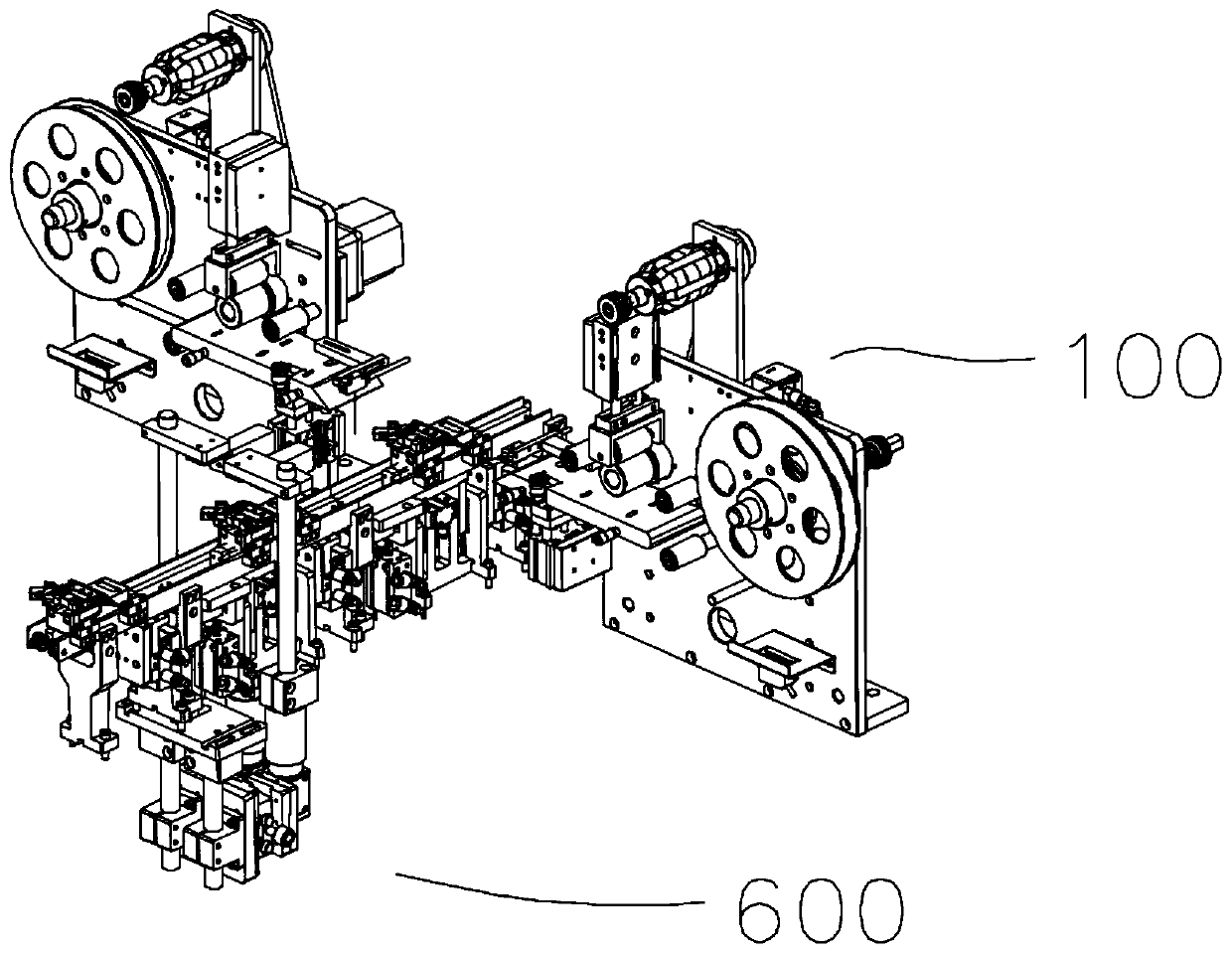
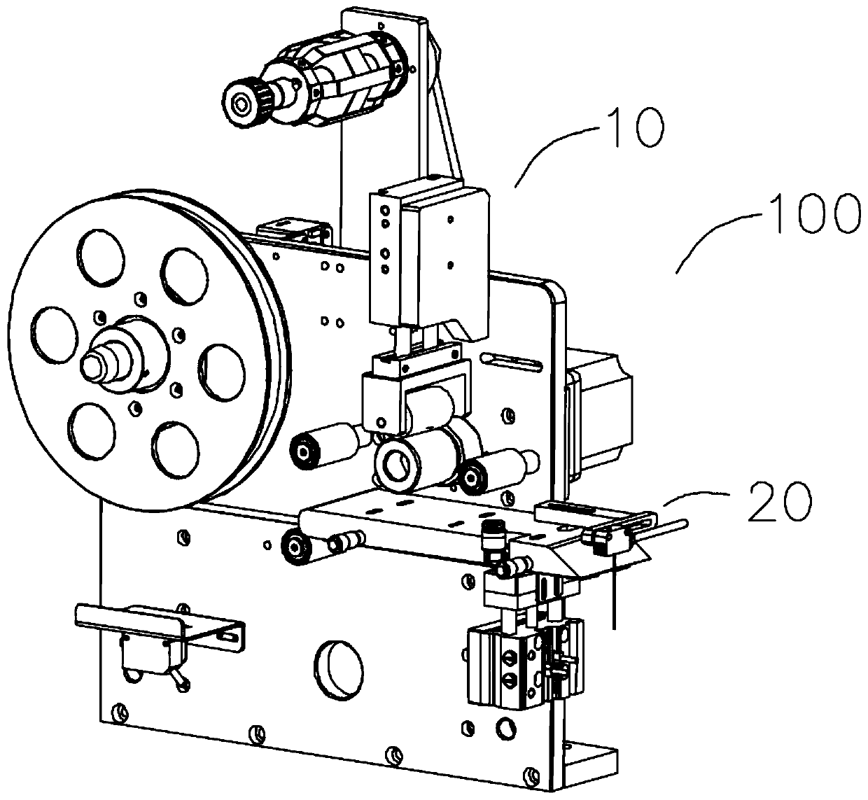
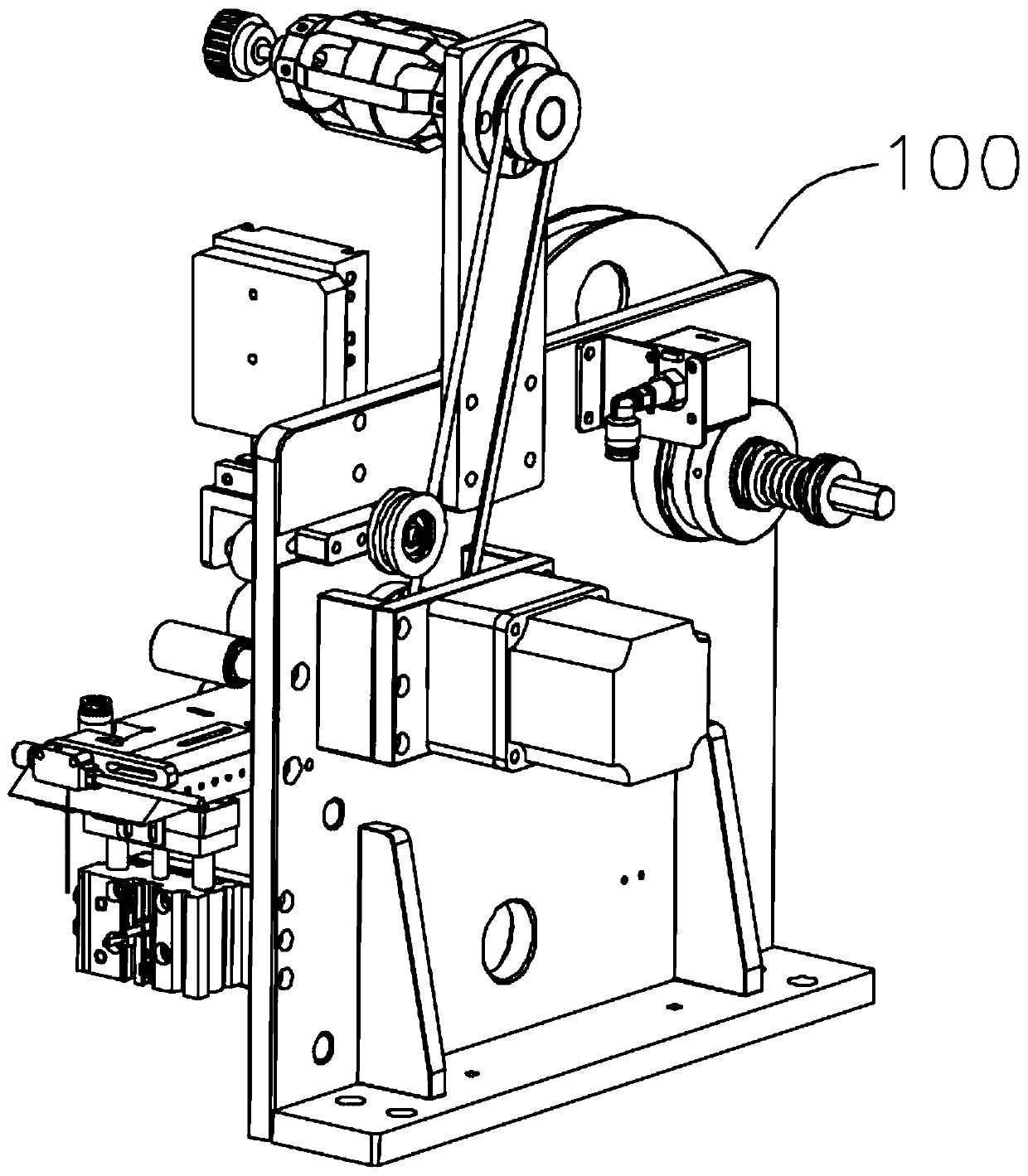
Stripping and shooting mechanism

A technology of peeling mechanism and winding mechanism, applied in the field of automation, can solve the problem of low degree of automation, and achieve the effects of high positioning accuracy, high peeling efficiency and high degree of automation

Pending Publication Date: 2019-06-11
启翊创智能科技(苏州)有限公司
View PDF0 Cites 0 Cited by
  • Summary
  • Abstract
  • Description
  • Claims
  • Application Information

AI Technical Summary

Problems solved by technology

[0003] In order to overcome the deficiencies in the prior art, one of the purposes of the present inven

Method used


Image

  • Stripping and shooting mechanism
  • Stripping and shooting mechanism
  • Stripping and shooting mechanism

Examples


Example Embodiment

[0038] Below, the present invention will be further described in conjunction with the accompanying drawings and specific implementation methods. It should be noted that, under the premise of not conflicting, the various embodiments described below or the technical features can be combined arbitrarily to form new embodiments. .

[0039] It should be noted that when a component is said to be "fixed" to another component, it can be directly on the other component or there can also be an intervening component. When a component is said to be "connected" to another component, it may be directly connected to the other component or there may be intervening components at the same time. When a component is said to be "set on" another component, it may be set directly on the other component or there may be an intervening component at the same time. The terms "vertical," "horizontal," "left," "right," and similar expressions are used herein for purposes of illustration only.

[0040]Unl...


PUM


Abstract

The invention discloses a stripping and shooting mechanism. The stripping and shooting mechanism comprises a stripping mechanism and a shooting mechanism; the stripping mechanism comprises a winding mechanism and a stripping and pressing mechanism; the stripping and pressing mechanism comprises a stripping main body; the shooting mechanism comprises a position detecting mechanism and a front end belt module; the position detecting mechanism comprises a position detecting camera; the front end belt module comprises a conveying structure, a stabilizing frame, a stop structure and a positioning structure; the conveying structure comprises a side shielding piece, a conveying wheel and a belt; the stop structure comprises a stop cylinder and a stop piece; when fixtures are conveyed along a beltto reach a stop position in use, the stop cylinder drives the stop piece to move to stop the fixtures to prevent excessive conveying of the fixtures; and when the stop position is continuously shifted to reach a positioning position, a first side stop cylinder drives the side stop piece to move to stop from the left side, the stripping mechanism strips patches, and the position detecting camera is aligned to the patches on the fixtures, so that the masses and the positions of the patches are shot and detected, and the automation degree is high.

Description

technical field [0001] The invention relates to the field of automation, in particular to a stripping and photographing mechanism. Background technique [0002] At present, with the improvement of people's living standards and the rapid development of society, more and more automation equipment has entered the production process, and improving production efficiency has become one of the important goals of the factory. However, in the process of using the existing labeling device, people generally need to participate manually, the degree of automation is low, which affects the production efficiency, and the positioning effect is poor during the transmission process. Some equipment adopts a positioning structure, but the commonly used positioning structure positioning Low efficiency and low positioning accuracy affect the subsequent production and processing; in the process of use, the stripping efficiency of the patch is low and the detection effect is poor, which affects the...

Claims


Application Information

Patent Timeline
IPC IPC(8): B65C9/18B65C9/36B65C9/40
Inventor 周锐王展张新军刘东生
Owner 启翊创智能科技(苏州)有限公司
Why Eureka
Try Eureka