
A method for decoupling multiple transmitting coils placed in a single row in a wireless power transfer system

A technology of wireless power transmission and transmitting coils, which is applied in transmission systems, near-field transmission systems, circuit devices, etc., can solve the problems of reducing system efficiency, increasing the difficulty of system control, and unable to solve the coupling of transmitting coils, so as to improve transmission efficiency, The effect of reducing the difficulty of system control

Active Publication Date: 2020-12-15
ZHEJIANG UNIV
View PDF3 Cites 0 Cited by
  • Summary
  • Abstract
  • Description
  • Claims
  • Application Information

AI Technical Summary

Problems solved by technology

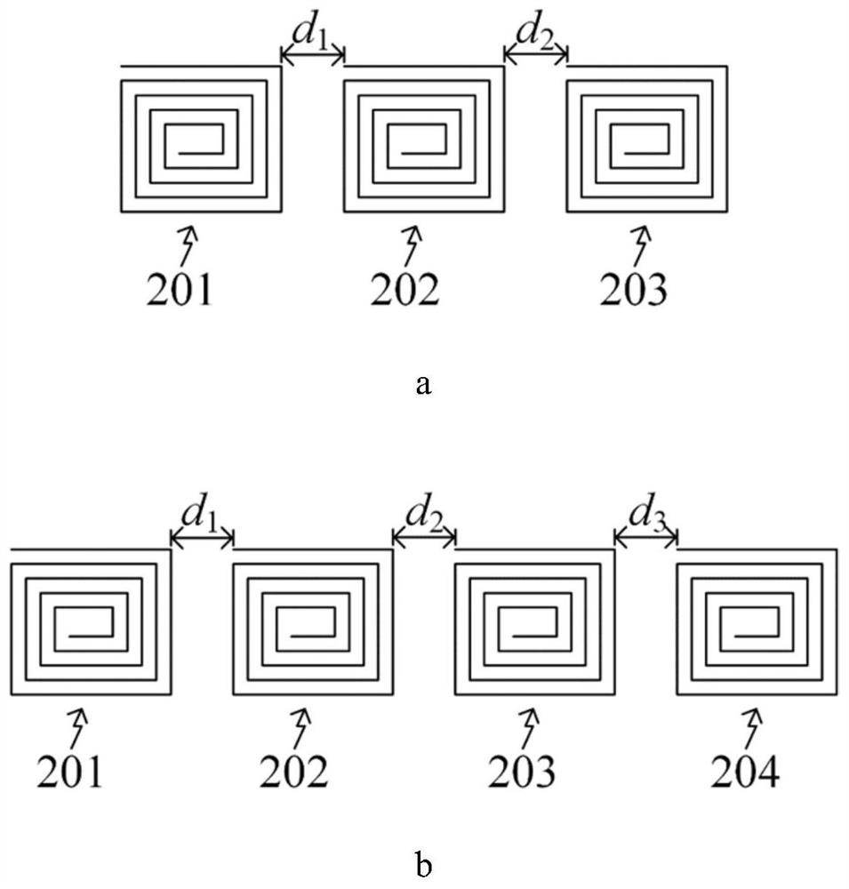
[0004] Existing methods only eliminate or partially eliminate the coupling between adjacent transmitting coils through common reactance, but cannot solve the problem of coupling between two transmitting coils when one transmitting coil is separated
As mentioned earlier, the coupling between two transmitting coils when separated by one transmitting coil will reduce the system efficiency, and it will also make the system more difficult to control

Method used


Image

  • A method for decoupling multiple transmitting coils placed in a single row in a wireless power transfer system
  • A method for decoupling multiple transmitting coils placed in a single row in a wireless power transfer system
  • A method for decoupling multiple transmitting coils placed in a single row in a wireless power transfer system

Examples


Embodiment Construction

[0027] The detailed description set forth below in conjunction with the appended drawings is intended as a description of exemplary embodiments of the invention and is not intended to represent the only embodiments in which the invention may be practiced. The term "exemplary" is used throughout this description to mean "serving as an example, instance, or illustration," and should not necessarily be considered preferred or advantageous over other exemplary embodiments. The detailed description contains specific details in order to provide a thorough understanding of the exemplary embodiments of the invention. In some instances, devices are shown in block diagram form.

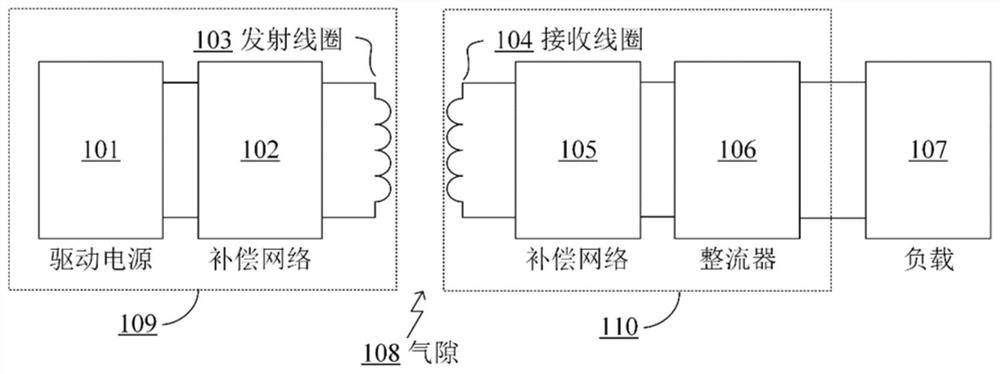
[0028] figure 1 is a functional structural block diagram of a wireless power transmission system according to all exemplary embodiments of the present invention. The power transmitter 109 includes a driving power source 101 , a compensation network 102 and a transmitting coil 103 . The driving power supply ...


PUM


Abstract

The invention discloses a method for achieving decoupling of multiple emission coils arranged in a single row of a wireless electric energy transmission system. The system according to the method comprises N emission coils, wherein N is more than or equal to 3, and all emission coils are arranged in a single row. According to the method, a common branch reactance component is arranged between coupled power emitters, and inductance between the two emission coils comprising the common branch reactance component is eliminated by configuration. By the method, the inductance between two adjacent emission coils can be eliminated, and the inductance between the two emission coils isolated by one of the emission coils also can be eliminated. By the method, the system transmission efficiency is improved, and the system control difficulty is reduced.

Description

technical field [0001] The invention relates to wireless power transmission technology, in particular to a method for realizing decoupling of multiple transmitting coils placed in a single row in a wireless power transmission system. Background technique [0002] Due to its safe and convenient features, wireless power transmission technology is widely used in various electrical equipment, such as mobile terminals, medical equipment, and electric vehicles. In order to increase the transmission distance of the wireless power transfer system, a wireless power transfer system with multiple transmitting coils may be used for power transmission. However, due to the coupling among multiple transmitting coils, not only will the system efficiency be reduced, but also the control difficulty of the system will be increased. [0003] Currently, "System and Method for Decoupling Multiple Wireless Charging Transmitters" (Patent No.: CN104584446A) provides a method for decoupling multiple...

Claims


Application Information

Patent Timeline
Patent Type & Authority Patents(China)
IPC IPC(8): H02J50/10H02J50/40H01F38/14H04B5/00
Inventor 钟文兴方赞峰徐德鸿
Owner ZHEJIANG UNIV
Learn More