Camera control system, camera control method and mobile terminal

A mobile terminal and control system technology, applied in the field of communication, can solve the problems of complex control logic and high cost

Inactive Publication Date: 2019-06-11
VIVO MOBILE COMM CO LTD
View PDF7 Cites 16 Cited by
  • Summary
  • Abstract
  • Description
  • Claims
  • Application Information

AI Technical Summary

Problems solved by technology

[0006] In view of this, in order to solve the problem that the cost of the camera control system is relatively high and the control logic is relatively complicated in the existing mobile terminal, the embodiment of the present invention proposes a camera control system, a camera control method and a mobile terminal

Method used


Image

  • Camera control system, camera control method and mobile terminal
  • Camera control system, camera control method and mobile terminal
  • Camera control system, camera control method and mobile terminal

Examples


Embodiment 1

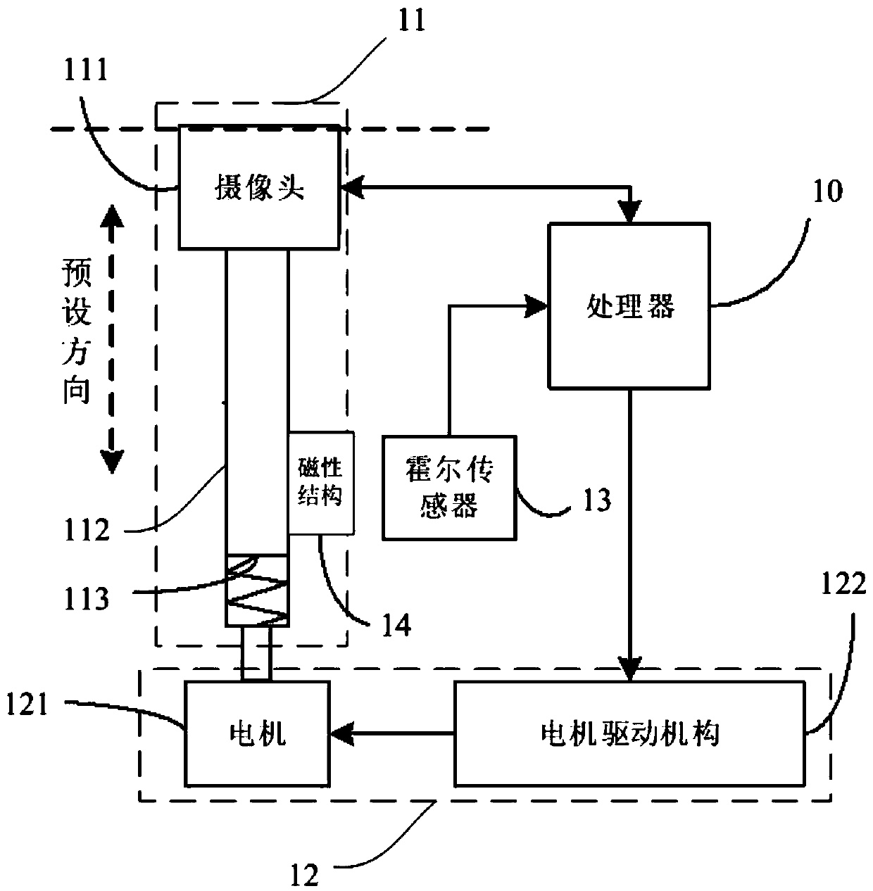
[0024] refer to figure 1 , shows a schematic structural diagram of a camera control system of the present invention, the system can be applied to mobile terminals, and the system can specifically include: a processor 10, a camera assembly 11, a drive structure 12, a Hall sensor 13 and a magnetic structure 14 .

[0025] Wherein, the driving structure 12 is connected with the camera assembly 11 and the processor 10 respectively, and drives the camera assembly 11 to move along a preset direction.

[0026] The magnetic structure 14 is fixed on the camera assembly 11 or the driving structure 12 .

[0027] The Hall sensor 13 is connected to the processor 10 and is fixedly installed in the mobile terminal. When the driving structure 12 drives the camera assembly 11 to move, the distance between the Hall sensor 13 and the magnetic structure 14 changes.

[0028] In the embodiment of the present invention, since the magnetic structure 14 is fixed on the camera head assembly 11 or the ...

Embodiment 2

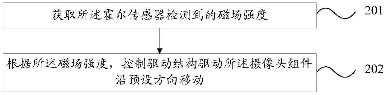
[0065] refer to figure 2 , which shows a flow chart of the steps of a camera control method of the present invention, the method can be applied to the above camera control system, and the method can specifically include:

[0066] Step 201: Obtain the magnetic field strength detected by the Hall sensor.

[0067] In the embodiment of the present invention, since the magnetic structure is fixed on the camera assembly or the driving structure, during the movement of the camera assembly along the preset direction, the magnetic structure can follow the The components or the drive structure move together. As the magnetic structure moves, the magnetic field strength of the magnetic structure detected by the Hall sensor will also change accordingly.

[0068] In the embodiment of the present invention, the movement of the camera assembly along the preset direction may include extending movement and retracting movement. Specifically, the camera assembly can extend from the inside of ...

Embodiment 3

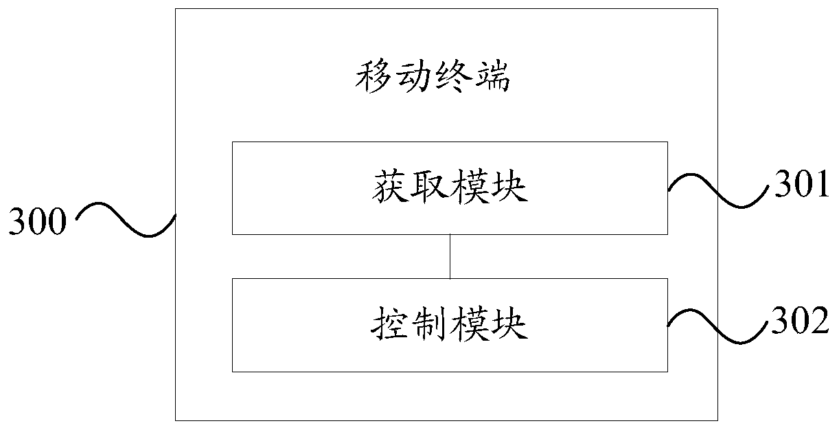
[0087] refer to image 3 , shows a structural block diagram of a mobile terminal according to the present invention, specifically, the mobile terminal may include but not limited to any one of a mobile phone, a tablet computer, and a wearable device. The mobile terminal 300 may specifically include:

[0088] The obtaining module 301 is configured to obtain the magnetic field strength detected by the Hall sensor.

[0089] The control module 302 is configured to control the driving structure to drive the camera assembly to move in a preset direction according to the strength of the magnetic field.

[0090] Optionally, when the camera assembly moves to a first preset position, the Hall sensor is flush with the magnetic structure, and the first preset position is when the camera moves along the preset direction Retracting the mobile terminal to an extreme position.

[0091] Then the control module 302 may include:

[0092] The first extension control submodule is configured to...


PUM


Abstract

The embodiment of the invention provides a camera control system, a camera control method and a mobile terminal, and relates to the technical field of communication. The camera control system comprises a processor, a camera assembly, a driving structure, a Hall sensor and a magnetic structure, wherein the driving structures are respectively connected with the camera assembly and drive the camera assembly to move along a preset direction; the magnetic structure is fixed on the camera assembly or the driving structure; and the Hall sensor is connected with the processor and is fixedly arranged in the mobile terminal, and when the driving structure drives the camera assembly to move, the distance between the Hall sensor and the magnetic structure is changed.

Description

technical field [0001] The present invention relates to the field of communication technology, in particular to a camera control system, a camera control method and a mobile terminal. Background technique [0002] With the development of full-screen mobile terminals and the gradual improvement of user experience, the display areas of mobile terminals such as mobile phones and tablet computers are getting larger and larger, and the screen-to-body ratio is also getting higher and higher. [0003] In order to avoid the impact on the screen-to-body ratio of the mobile terminal by opening a hole on the screen to place the front camera, a retractable front camera is often used in the existing technology. In the case of using the front camera for selfie, the front camera can protrude from the inside of the mobile terminal, and in the case of no need to use the front camera, the front camera can be retracted into the inside of the mobile terminal without affecting the movement The ...

Claims


Application Information

Patent Timeline
Patent Type & Authority Applications(China)
IPC IPC(8): H04N5/232G05D3/12
Inventor 陈凯
Owner VIVO MOBILE COMM CO LTD
Why Eureka
Try Eureka