
Wind resistance braking device

A windage braking and driving device technology, applied in the direction of brakes, braking components, railway braking systems, etc., can solve the problems of needing shrouds, slow starting speed, complex structure, etc.

Active Publication Date: 2019-06-14
CRRC QINGDAO SIFANG ROLLING STOCK RES INST
View PDF8 Cites 18 Cited by
  • Summary
  • Abstract
  • Description
  • Claims
  • Application Information

AI Technical Summary

Problems solved by technology

Although the "cat ears" type wind resistance braking device can provide a large braking force, its structure is complex and heavy, and it will take up a lot of space in the compartment when it is stored, which does not meet the requirements of miniaturization and light weight; the small distributed wind resistance brake The brake device adopts the method of two wind resistance brake plates to cancel each other's torque. The brake device starts quickly and has a small storage space. However, there is a certain angle difference between the two brake plates in the braking position, which will cause vortex airflow. And vibration, which has a certain impact on the stability of the train; the hydraulic windage brake device is bulky in structure, requires a large modification of the car body, and requires a shroud. The design of the mechanism is unreasonable, and it can only be started in one direction, not applicable to two A running train with hydraulic start, slow start speed, etc.

Method used


Image

  • Wind resistance braking device
  • Wind resistance braking device
  • Wind resistance braking device

Examples


Embodiment Construction

[0028] Hereinafter, the present application will be specifically described through exemplary implementations. It should be understood, however, that elements, structures and characteristics of one embodiment may be beneficially incorporated in other embodiments without further recitation.

[0029] In the description of the present application, it should be noted that the orientation or positional relationship indicated by the terms "inner", "outer", "upper", "lower", "front", "rear" etc. are based on the The positional relationship is only for the convenience of describing the present invention and simplifying the description, but does not indicate or imply that the referred device or element must have a specific orientation, be constructed and operated in a specific orientation, and thus should not be construed as limiting the present invention. The connection may refer to a direct connection relationship or an indirect connection relationship; in addition, the terms "first",...


PUM


Abstract

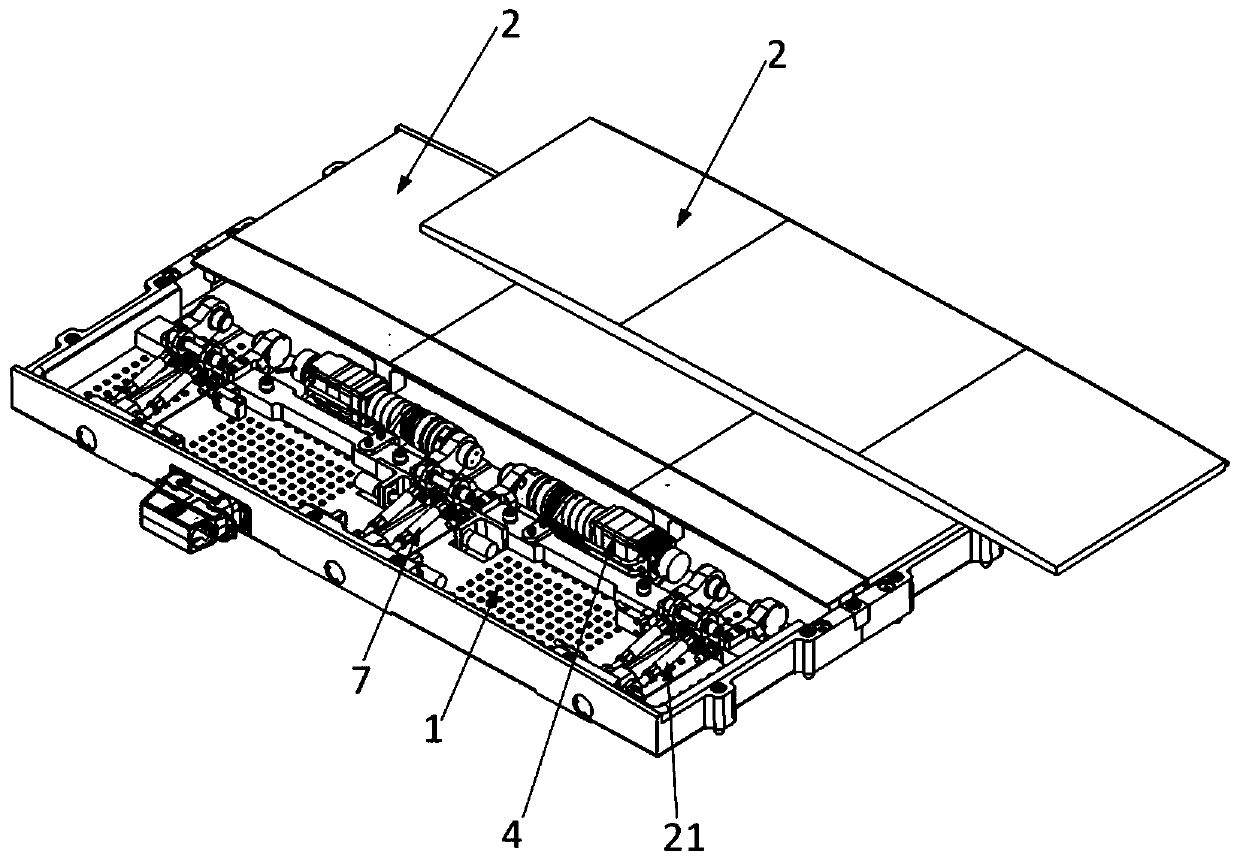
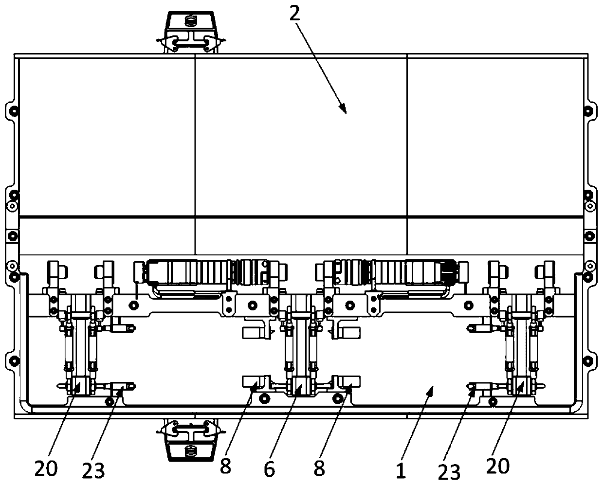
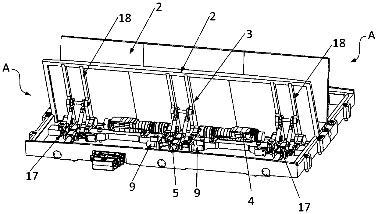
The invention relates to a wind resistance braking device. The device comprises at least one first component, each component comprises a base, a brake plate which is provided with a first extension part, a driving device capable of controlling opening or closing of the brake plate, a first guide rail and a first sliding block thereon, and each first slide block is provided with a first protrusionend; one end of a first pull rod is rotatably connected with the corresponding first slide block, and the other end of each pull rod is rotatably connected with the corresponding first extension part;a first electronic control lock is arranged on the portion close to the first end of the corresponding first guide rail, and a second electronic control lock is arranged on the portion close to the second end of the corresponding first guide rail; each first component further comprises a control unit electrically connected with the corresponding driving device, the corresponding first electroniccontrol lock and the corresponding second electronic control lock, wherein the control unit can control the driving device to run and drives the corresponding first extension part to open or close thecorresponding brake plate; the control units can control the electronic control locks to limit or do not limit the first protrusion ends.

Description

technical field [0001] The application belongs to the field of braking, and in particular relates to a wind resistance braking device. Background technique [0002] Wind resistance braking is a new way of high-speed train braking, which uses wind baffles to increase air resistance to generate braking force. When the train is running at high speed, the surrounding air exerts a force on the train opposite to the direction of its motion. At this time, the wind blocking plate is opened outward from the surface of the streamlined train, and the braking force that directly decelerates the train is generated due to air resistance. Since the aerodynamic resistance is proportional to the square of the speed, the higher the speed, the greater the braking force, so the wind resistance braking method has excellent characteristics when braking at high speed. [0003] At present, a variety of wind resistance braking devices have been developed at home and abroad, such as "cat ears" wind...

Claims


Application Information

Patent Timeline
IPC IPC(8): B60T1/16B61H11/00
Inventor 汤劲松杨磊尹崇宏马飞周宇航王帅
Owner CRRC QINGDAO SIFANG ROLLING STOCK RES INST
Learn More