
Pushing rolling mechanism and walking-vehicle bottom frame

A traveling vehicle and underframe technology, which is applied in the directions of motor vehicles, substructures, vehicle components, etc., can solve the problems of increasing the energy loss of driving vehicles, occupying a large space for traveling vehicles, and driving tank trucks intermittently, and achieves smooth fluctuation and versatility. Strong, low resistance effect

Pending Publication Date: 2019-06-14
陈建军
View PDF0 Cites 2 Cited by
  • Summary
  • Abstract
  • Description
  • Claims
  • Application Information

AI Technical Summary

Problems solved by technology

Generally, the trolley is used to push the tank truck for loading and unloading. Because the road surface of the construction site is often uneven, the push-roll mechanism in front of the trolley cannot continuously contact with the tank truck in front, resulting in intermittent pushing of the tank truck, which affects unloading. The uniformity of the material increases the energy loss of driving the vehicle
In addition, the trolley takes up a lot of space, and the current trolley has a single function and is not universal
There are too many trolleys on the construction site, which takes up a lot of space. Due to the single function of the trolley, temporary modification is very time-consuming and laborious.

Method used


Image

  • Pushing rolling mechanism and walking-vehicle bottom frame
  • Pushing rolling mechanism and walking-vehicle bottom frame
  • Pushing rolling mechanism and walking-vehicle bottom frame

Examples


Embodiment 1

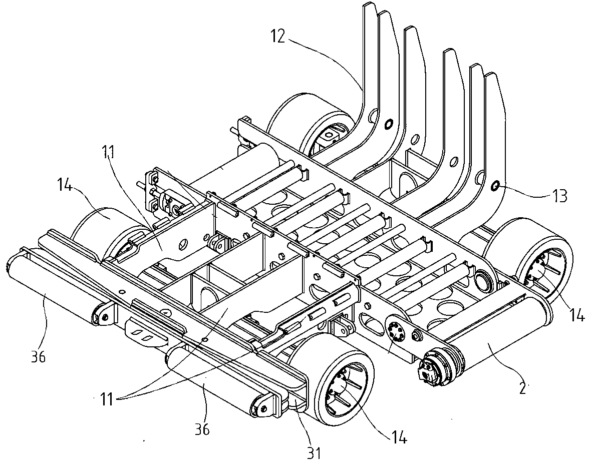
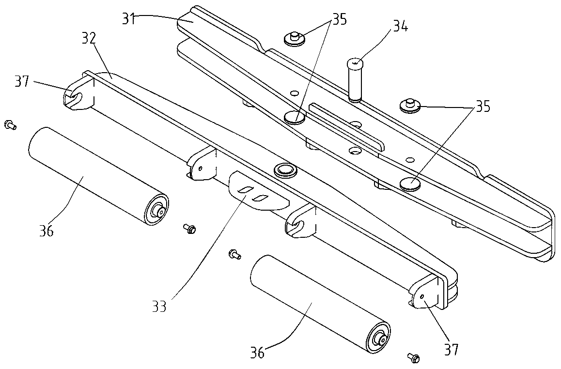
[0028] Embodiment 1, the rolling mechanism 3 is fixedly connected to the bottom frame. The rear end of the pushing and rolling mechanism 3 is provided with an inserting arm 31 connected with the chassis and fixed with a bolt. The above-mentioned underframe of the traveling vehicle also includes several rear beams 12 arranged in parallel, a conveying mechanism 2 is provided between the front beams 11 and the rear beams 12 , and a rear bridge 123 is provided below the rear beams 12 .

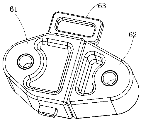
[0029] The above-mentioned trolley underframe, the rear end of the underframe is provided with a pin block to connect the drive car for providing power, the pin block includes a groove pin block 61, a boss pin block 62 and a pin 63, the Groove pin block 61 is hinged at the front end of the driving car, and described boss pin block 62 is hinged at the bottom frame rear end, and is fixed with described pin 63 after groove pin block 61 and boss pin block 62 are inserted and matched.

Embodiment 2

[0030] Embodiment 2. The difference between this embodiment and Embodiment 1 is that the push-rolling mechanism 3 and the bottom frame are connected through an adjustable plug-in connection through the connecting arm 38, and the connecting arm 38 is plugged into the bottom frame through a bolt. , The plugging position can be adjusted as required, and the assembly position of the push-roll mechanism 3 can be adjusted according to the front unloading wheel base under different working conditions.


PUM


Abstract

The invention provides a pushing rolling mechanism. The pushing rolling mechanism comprises a pushing rolling beam with a U-shaped-groove cross section, a swinging arm beam with a U-shaped-groove cross section and two rollers arranged at the front end of the swinging arm beam; the swinging arm beam is hinged into the U-shaped groove of the pushing rolling beam through a swinging arm pin shaft vertically arranged in the middle of the swinging arm beam. The invention also provides a walking-vehicle bottom frame provided with the pushing rolling mechanism, and through the pushing rolling mechanism, good contact exists between a walking vehicle and a front tank truck. The universality of the walking vehicle is high, field refitting is convenient, assembly line production can be achieved, and the manufacturing cost is greatly reduced.

Description

technical field [0001] The invention belongs to the mechanical field of trolley attachments, and in particular relates to a push-roll mechanism and a chassis of a trolley. Background technique [0002] In construction machinery construction vehicles, in many occasions, it is necessary to have a driving host to drive a traveling vehicle attachment with certain functions. Generally, the trolley is used to push the tank truck for loading and unloading. Because the road surface of the construction site is often uneven, the push-roll mechanism in front of the trolley cannot continuously contact with the tank truck in front, resulting in intermittent pushing of the tank truck, which affects unloading. The uniformity of the material will increase the energy loss of driving the vehicle. In addition, the trolley takes up a lot of space, and the current trolley has a single function and is not universal. There are too many trolleys on the construction site, which occupy a lot of spa...

Claims


Application Information

Patent Timeline
Patent Type & Authority Applications(China)
IPC IPC(8): B62D21/18B62D63/04
Inventor 陈建军
Owner 陈建军
Learn More