

Sky drawing method and device, equipment and medium
A sky and screen display technology, applied in image data processing, 3D modeling, instruments, etc., can solve problems such as computational troubles, and achieve the effect of reducing computational complexity
- Summary
- Abstract
- Description
- Claims
- Application Information
AI Technical Summary
Problems solved by technology
Method used
Image

Examples
Embodiment 1
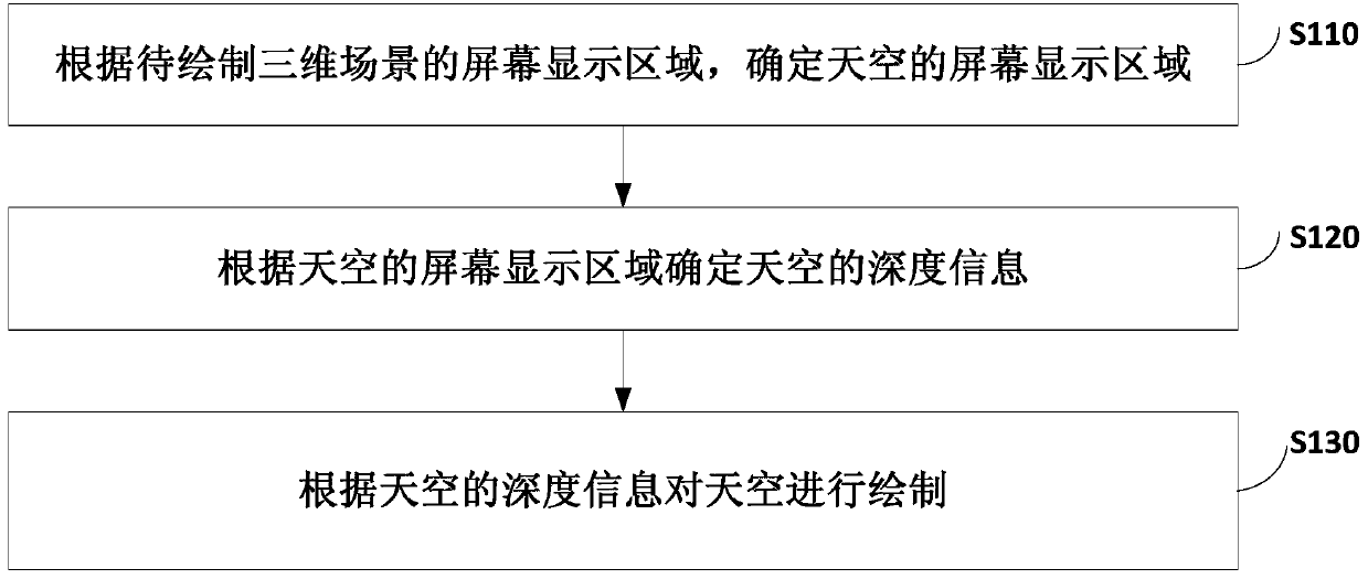
[0033] figure 1 It is a flowchart of a sky rendering method provided by Embodiment 1 of the present invention. This embodiment is applicable to the situation of drawing the sky in a three-dimensional scene, and the three-dimensional scene may be a scene of a three-dimensional electronic map. Typically, this embodiment is applicable to rendering scenarios that cannot be precisely controlled within the range of a three-dimensional electronic map and require depth information in the sky. The method can be executed by a sky rendering device, and the device can be realized by software and / or hardware. see figure 1 , the sky rendering method provided by the embodiment of the present invention includes:
[0034] S110. Determine the screen display area of the sky according to the screen display area of the 3D scene to be drawn.
[0035] Wherein, the three-dimensional scene to be drawn may be any scene presenting three-dimensional visual effects.
[0036] Typically, the three-...
Embodiment 2
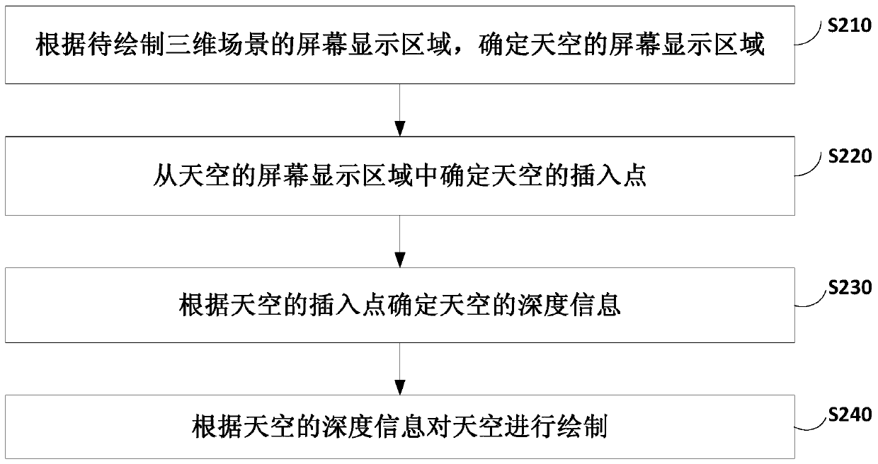
[0068] figure 2 It is a flow chart of a sky rendering method provided by Embodiment 2 of the present invention. This embodiment is an optional solution proposed on the basis of the foregoing embodiments. see figure 2 , the sky rendering method provided by this embodiment includes:
[0069] S210. Determine the screen display area of the sky according to the screen display area of the 3D scene to be drawn.
[0070] S220. Determine an insertion point of the sky from the screen display area of the sky.
[0071] Wherein, the insertion point of the sky refers to the point where the sky is inserted.
[0072] Optionally, the insertion point of the sky may be any point in the display area of the screen.
[0073] Typically, the determining the insertion point of the sky from the screen display area of the sky includes:
[0074] Determine the connecting line between the screen display area of the sky and the screen display area of the ground in the 3D scene to be dr...
Embodiment 3
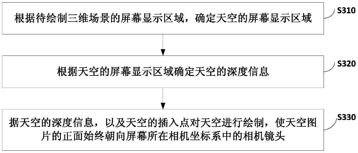
[0085] image 3 It is a flow chart of a sky rendering method provided by Embodiment 3 of the present invention. This embodiment is an optional solution proposed on the basis of the foregoing embodiments. see image 3 , the sky rendering method provided by this embodiment includes:
[0086] S310. Determine the screen display area of the sky according to the screen display area of the 3D scene to be drawn.
[0087] S320. Determine the depth information of the sky according to the screen display area of the sky.
[0088] S330. Draw the sky according to the depth information of the sky and the insertion point of the sky, so that the front of the sky picture always faces the camera lens in the camera coordinate system where the screen is located.
[0089] Typically, the sky can be drawn based on the method of drawing billboards in OpenGL.
[0090] Specifically, the sky is drawn according to the insertion point of the sky, so that the front of the sky picture is always fa...
PUM
 Abstract
Description
Claims
Application Information