Supercharge Your Innovation With Domain-Expert AI Agents!

Card tray locking ejection mechanism, card tray fixing device and electronic equipment

A technology of electronic equipment and ejection mechanism, which is applied in the direction of coupling device, parts of connecting device, device for connecting/disconnecting connecting parts, etc. Inside the battery cover, etc.

Active Publication Date: 2020-11-13
SHANGHAI MORUAN COMM TECH
View PDF14 Cites 0 Cited by
  • Summary
  • Abstract
  • Description
  • Claims
  • Application Information

AI Technical Summary

Problems solved by technology

[0003] For this locking structure, firstly, the battery cover needs to open a hole to use the thimble to push out the SIM card tray. If there is no thimble by your side, there is no way to take out the SIM card. When the structural design is not in place, the thimble will push against the card holder. The phenomenon that the terminal block is stuck in the battery cover

Method used


Image

  • Card tray locking ejection mechanism, card tray fixing device and electronic equipment
  • Card tray locking ejection mechanism, card tray fixing device and electronic equipment

Examples


Embodiment Construction

[0022] In order to make the object, technical solution and advantages of the present invention clearer, various embodiments of the present invention will be described in detail below in conjunction with the accompanying drawings. However, those of ordinary skill in the art can understand that, in each implementation manner of the present invention, many technical details are provided for readers to better understand the present application. However, even without these technical details and various changes and modifications based on the following implementation modes, the technical solution claimed in this application can also be realized.

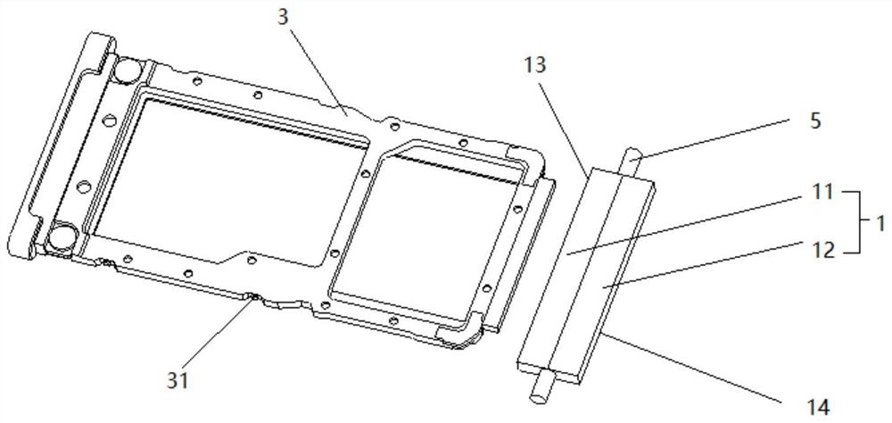
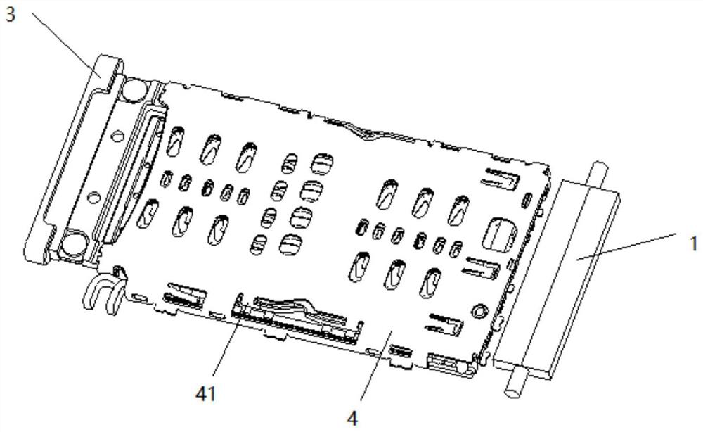
[0023] The first embodiment of the present invention relates to a card tray locking and ejecting mechanism, which is used for locking or ejecting a card tray 3 inserted into an electronic device.

[0024] Such as figure 1 As shown, in this embodiment, the locking and ejecting mechanism of the card tray 3 includes: a magnetic part 1 arrange...


PUM


Abstract

The invention relates to the field of electronic equipment. The embodiment of the invention provides a card support locking and pop-out mechanism, a card support fixed device and electronic equipment.The card support locking and pop-out mechanism comprises magnetic piece and a driving piece, wherein the magnetic piece is arranged in a shell of the electronic equipment and is arranged opposite toa card seat along a direction of the card support inserted into the card seat, the magnetic piece is provided with a first magnetic side and a second magnetic side, the polarity of the first magneticside is opposite to the polarity of the second magnetic side, the first magnetic side is used for attracting a magnetic part arranged at a front end of the card support, the second magnetic side is used for repelling the magnetic part arranged at the front end of the card support, the driving piece is arranged in the shell, is connected with the magnetic piece and is used for driving the magneticpiece to rotate along arrangement directions of the first magnetic side and the second magnetic side, the first magnetic side is further used for being opposite to the card seat when the magnetic piece is rotated to a first preset position by the driving piece, and the second magnetic side is further used for being opposite to the card seat when the magnetic piece is rotated to a second preset position by the driving piece.

Description

technical field [0001] The invention relates to electronic equipment accessories, in particular to a card tray locking and ejecting mechanism, a card tray fixing device and electronic equipment. Background technique [0002] The locking device of the current SIM card tray is mainly on the SIM card holder of the main board. At this time, use the thimble to push the end platform next to the card holder, and the end platform moves downward to drive the lever at the bottom of the card holder to move upward to eject the SIM card. [0003] For this locking structure, firstly, the battery cover needs to open a hole to use the thimble to push out the SIM card tray. If there is no thimble by your side, there is no way to take out the SIM card. When the structural design is not in place, the thimble will push against the card holder. The terminal block is stuck inside the battery cover. Contents of the invention [0004] The object of the present invention is to provide a card tra...

Claims


Application Information

Patent Timeline
Patent Type & Authority Patents(China)
IPC IPC(8): H01R13/502H01R13/62H01R13/629
Inventor 赵义鹏
Owner SHANGHAI MORUAN COMM TECH
Features
  • R&D
  • Intellectual Property
  • Life Sciences
  • Materials
  • Tech Scout
  • Unparalleled Data Quality
  • Higher Quality Content
  • 60% Fewer Hallucinations
Learn More