
Epidermal thermal activation coating device

A coating device and thermal activation technology, applied in the direction of mechanical equipment, connecting components, etc., can solve the problems of affecting product quality, affecting the use effect, and weak coating force, so as to increase the pressure of air wrapping, avoid bulging of the foreskin, and improve The effect of product quality

Inactive Publication Date: 2019-06-18
成都佛吉亚汽车部件系统有限公司
View PDF6 Cites 0 Cited by
  • Summary
  • Abstract
  • Description
  • Claims
  • Application Information

AI Technical Summary

Problems solved by technology

[0002] At present, in the process of automobile manufacturing, it is necessary to cover the surface of the automobile instrument console shell, and the foreskin should be covered on the automobile instrument console shell coated with viscose, but due to the particularity of its material, only the covering Immediately after production will affect its use effect, because the covering force is not strong when covering, only relying on the adhesive force of its glue will cause the foreskin to bulge in the later stage, which will affect the product quality. Therefore, there is an urgent need for a wrapping The covered foreskin acts as a wrapping force and enhances the adhesion of the foreskin, so that the foreskin is squeezed by external force when the foreskin is glued together, and it is more tightly attached to the car instrument console shell, improving product quality

Method used


Image

  • Epidermal thermal activation coating device
  • Epidermal thermal activation coating device
  • Epidermal thermal activation coating device

Examples


Embodiment Construction

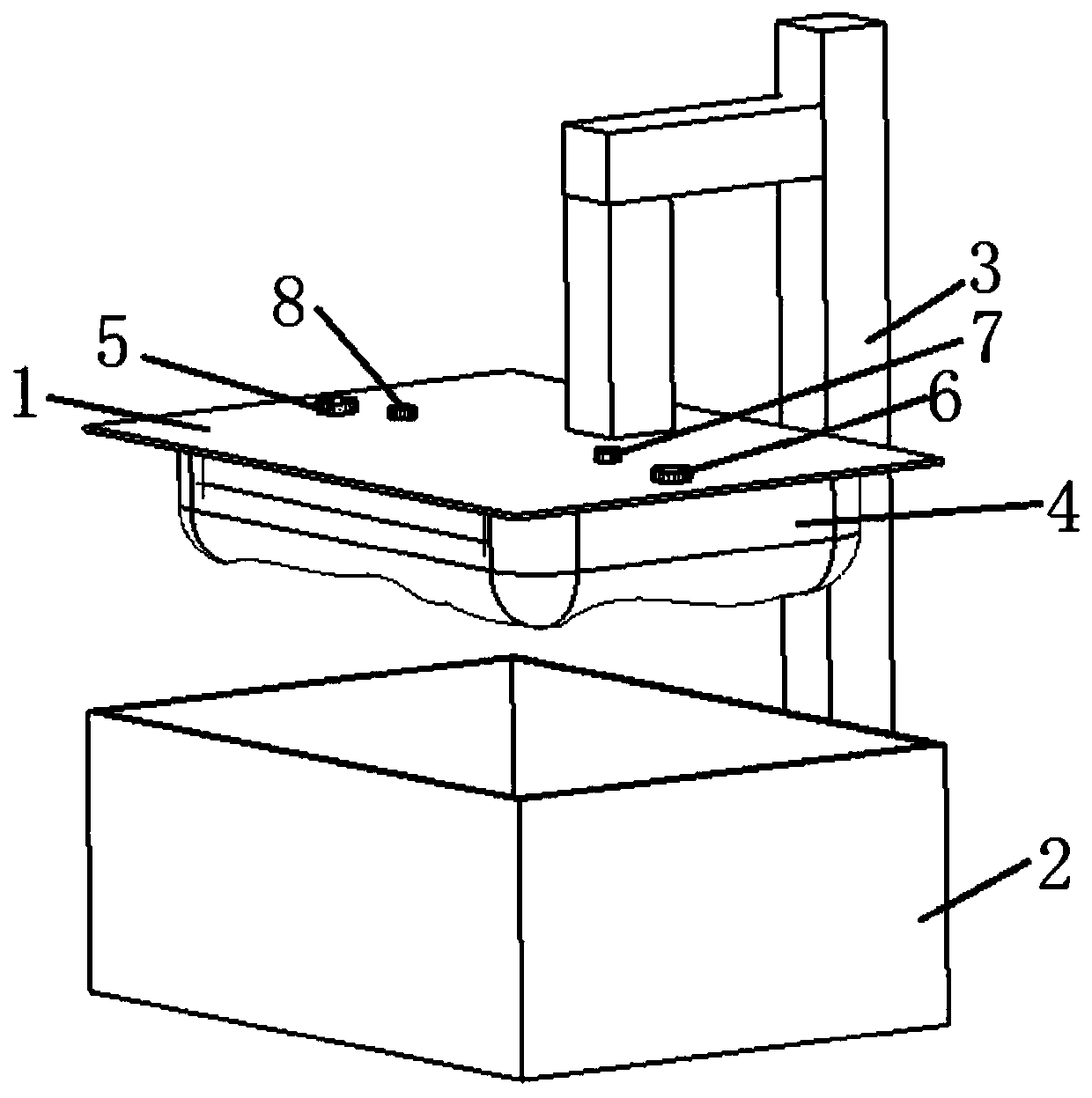
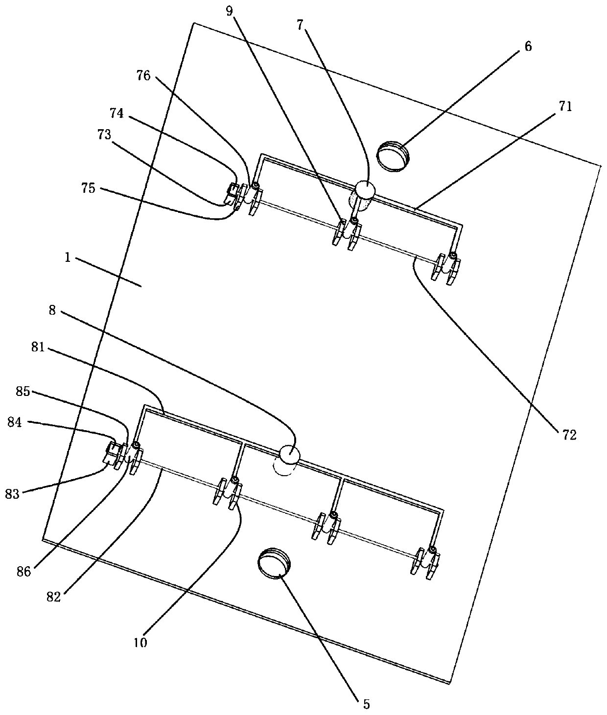
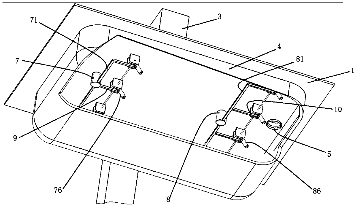
[0014] refer to Figure 1-5 , a skin heat activation coating device, including a lifting plate 1, a storage box 2, a lift 3, an air bag 4, an air inlet pipe 5, an air outlet pipe 6, a first high-pressure air inlet pipe 7, a second high-pressure air inlet pipe 8, a first The air injection mechanism 9 and the second air injection mechanism 10, the elevator 3 is connected to the lifting plate 1, the bottom of the lifting plate 1 is provided with an air bag 4, and the air inlet pipe 5, the air outlet pipe 6, and the first high pressure inlet pipe are arranged on the lifting plate 1. The air pipe 7 and the second high-pressure air intake pipe 8 communicate with the air bag 4, and the first air injection mechanism 9 and the second air injection mechanism 10 are symmetrically arranged in the bottom air bag 4 of the lifting plate 1, and the first air injection mechanism 9 and the first air injection mechanism The high-pressure intake pipe 7 communicates, the second air injection mecha...


PUM


Abstract

The invention discloses an epidermal thermal activation coating device. The epidermal thermal activation coating device comprises a lifting plate, a storage box, an elevator, an air bag, an air inletpipe, an air outlet pipe, a first high-pressure air inlet pipe, a second high-pressure air inlet pipe, a first air injection mechanism and a second air injection mechanism, wherein the elevator is connected with the lifting plate, the air bag is arranged at the bottom of the lifting plate, the air inlet pipe, the air outlet pipe, the first high-pressure air inlet pipe and the second high-pressureair inlet pipe communicated with the interior of the air bag are arranged on the lifting plate, the first air injection mechanism and the second air injection mechanism are symmetrically arranged in the bottom air bag of the lifting plate, the first air injection mechanism is in communication with the first high-pressure air inlet pipe, the second air injection mechanism is in communication with the second high-pressure air inlet pipe, and the storage box is arranged below the air bag. The wrapper adhered on a shell of an automobile instrument operation table is wrapped and pressed by the airbag, the air injection mechanisms in the air bag are adopted to carry out sweeping type high-pressure air injection on the air bag inner wall acting on the wrapper surface to press the air bag inner wall, the adhesive force of the wrapper is enhanced, the phenomenon that the wrapper is wrapped is avoided, and the product quality is improved.

Description

technical field [0001] The invention belongs to the technical field of surface treatment equipment, and mainly relates to a skin heat activation coating device. Background technique [0002] At present, in the process of automobile manufacturing, it is necessary to cover the surface of the automobile instrument console shell, and the foreskin should be covered on the automobile instrument console shell coated with viscose, but due to the particularity of its material, only the covering Immediately after production will affect its use effect, because the covering force is not strong when covering, only relying on the adhesive force of its glue will cause the foreskin to bulge in the later stage, which will affect the product quality. Therefore, there is an urgent need for a wrapping The covered foreskin acts as a wrapping force and enhances the adhesion of the foreskin, so that the foreskin is extruded by an external force when the foreskin is glued together so that it fits m...

Claims


Application Information

Patent Timeline
Patent Type & Authority Applications(China)
IPC IPC(8): F16B11/00
Inventor 朱国平彭福顺
Owner 成都佛吉亚汽车部件系统有限公司
Learn More