Floor mopping robot with position limiting rotational structure

A technology of a sweeping robot and a rotating structure, applied in the field of sweeping robots, can solve the problems of inability to move, the sweeping robot is stuck, hindering the sweeping robot from retreating, etc., and achieves the effect of good slope and steering functions.

Inactive Publication Date: 2019-06-21
SHARKNINJA CHINA TECH CO LTD
View PDF6 Cites 0 Cited by
  • Summary
  • Abstract
  • Description
  • Claims
  • Application Information

AI Technical Summary

Problems solved by technology

But at the same time, because the guide wheel has rotated 180°, the horizontal distance from the guide wheel to the central axis of the sweeping robot is obviously smaller than the distance when it is moving forward normally. According to the principle of leverage, the torque decreases and the pressure increases, and the bias device receives The pressure increases, which will drive the guide wheel and store part of it in the alcove, forming a tilted state in which the height of the rear of the base of the sweeping robot is lowered and the front is raised, such as figure 2 As shown, especially when the sweeping robot retreats to low-level ground obstacles such as carpets or floor mats on the ground, it will hinder the sweeping robot from retreating accordingly, and the sweeping robot may be stuck and unable to move

Method used


Image

  • Floor mopping robot with position limiting rotational structure
  • Floor mopping robot with position limiting rotational structure
  • Floor mopping robot with position limiting rotational structure

Examples


Embodiment 1

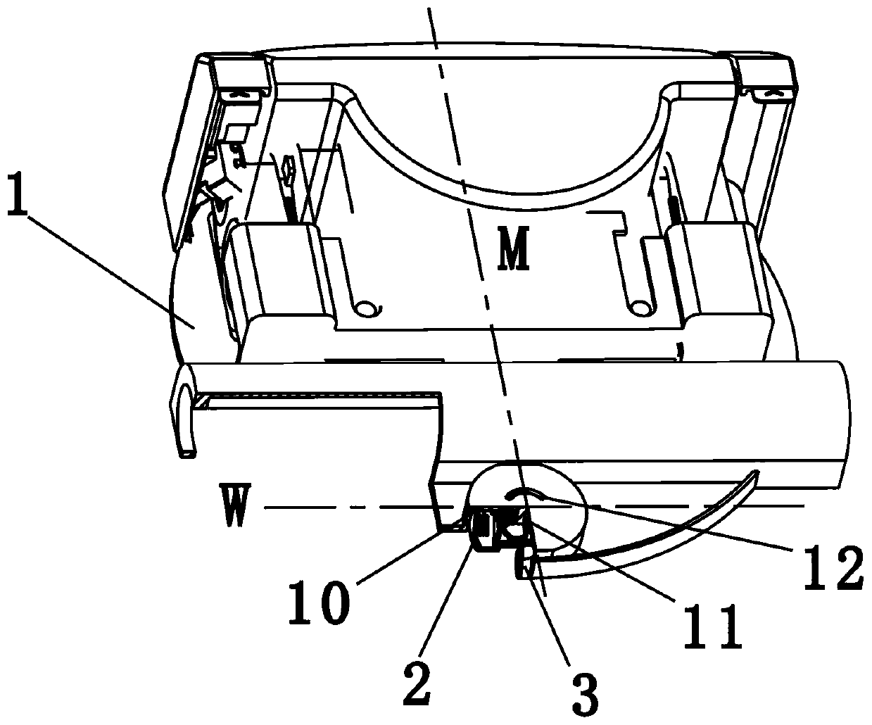
[0037] Such as image 3 , Figure 4 Shown is a schematic structural diagram of an embodiment of the present invention. A sweeping robot includes a base (not shown in the figure), a base at the bottom of the base 1, two traction units (not shown in the figure) installed on the base 1 and used to drive the base 1 and the base to move A biasing device 2 at the rear of the base and a guide wheel 3 mounted on the biasing device 2. The base 1 is provided with a mounting cavity 10, and the mounting cavity 10 is provided with a rotating shaft 11, and the biasing device 2 is mounted In the installation cavity 10 and rotates relative to the rotating shaft 11, and the biasing device 2 has a first position stored in the installation cavity 10 and a second position expanded from the installation cavity 10, in which a limit chute is provided 12. The biasing device 2 is provided with a rotation stop part that can slide on the limiting chute, and the biasing device 2 rotates around the rotatin...

Embodiment 2

[0049] Such as Picture 10 , Picture 11 Shown is a schematic structural diagram of another embodiment of the present invention. The difference between this embodiment and the first embodiment is that: in this embodiment, the limit chute 12 is located in the circumferential direction of the installation cavity, and the limit end is the end wall 121 of the upper limit chute on the circumferential wall of the installation cavity. The part is a first convex post 221 and a second convex post 222 which are arranged on the peripheral wall of the second rotating body 22 and protrude outward. When the first rotating body 21 drives the second rotating body 22 to rotate to the first convex post 221 or the second convex post 221 When the two protruding posts 222 abut against the end wall 121, the first rotating body stops rotating, wherein the first protruding post 221 and the second protruding post 222 are in a vertical plane relative to the line connecting the center of the second rotat...


PUM


Abstract

The invention relates to a home-use cleaning electric appliance, in particular to a floor mopping robot with a position limiting rotational structure. The floor mopping robot comprises a base body, abase, a traction unit and a guide wheel arranged on a bias voltage device, wherein an installing cavity is arranged on the base; a rotating shaft is arranged in the installing cavity; the bias voltagedevice is arranged in the installing cavity and rotates relative to the rotating shaft; a position limiting slide groove is formed in one of the installing cavity and the bias voltage device; a corresponding standstill locking part is arranged on the other one of the installing cavity and the bias voltage device; and the bias voltage device rotates around the rotating shaft in the position limiting rotational structure formed by the position limiting slide groove and the standstill locking part, wherein the center of the rotating shaft is used as a circle center, and the rotational angle of the bias voltage device is alpha, and is greater than 0 degree and smaller than 180 degrees. The floor mopping robot involved in the invention has the position limiting rotational structure for limiting the guide wheel to rotate 180 degrees, so that the base of the floor mopping robot cannot have an inclination state that the back end is low and the front end is high; and therefore, a stable advancing function of the floor mopping robot can be ensured.

Description

Technical field [0001] The invention relates to a household cleaning electrical appliance, in particular to a sweeping robot with a limit rotation structure. Background technique [0002] There is an invention patent application with the patent application number CN201480016918.3 and the invention title "Mobile Robot". The patent application discloses a mobile robot for floor cleaning, including a base, a body, a roughly circular outer cover and a separating device, as well as a traction unit installed at the front of the base and a biasing device installed at the rear of the base. The device is installed in the alcove of the base. Because the biasing device has a predetermined force, the guide wheel can be biased into the unfolded position. During the climbing process, the guide wheel can be partially stored in the alcove to realize a mobile robot Able to walk and clean under different road conditions. [0003] At the same time, the patent application also discloses a structure ...

Claims


Application Information

Patent Timeline
Patent Type & Authority Applications(China)
IPC IPC(8): A47L11/24A47L11/40
Inventor 王旭宁
Owner SHARKNINJA CHINA TECH CO LTD
Why Eureka
Try Eureka