
Retainer and steel ball assembly assembling mold and assembling method thereof

A technology for assembling molds and cages, which is applied in the direction of bearing components, shafts and bearings, mechanical equipment, etc., can solve the problems of easy finger injury and low production efficiency, and achieve the goal of improving product quality, increasing production efficiency, and reducing labor time costs Effect

Pending Publication Date: 2019-06-21
余姚市新丰轴承有限公司
View PDF3 Cites 0 Cited by
  • Summary
  • Abstract
  • Description
  • Claims
  • Application Information

AI Technical Summary

Problems solved by technology

[0003] The purpose of the present invention is to provide a cage and steel ball assembly assembly mold and its assembly method for the defects of the above-mentioned prior art that the ball filling method is manually filled one by one, the production efficiency is low, and the fingers are extremely easy to be injured. It can achieve the goal of multiple ball filling, high production efficiency and safety.

Method used


Image

  • Retainer and steel ball assembly assembling mold and assembling method thereof
  • Retainer and steel ball assembly assembling mold and assembling method thereof
  • Retainer and steel ball assembly assembling mold and assembling method thereof

Examples


Embodiment 1

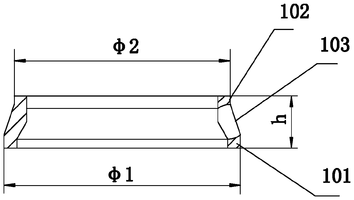
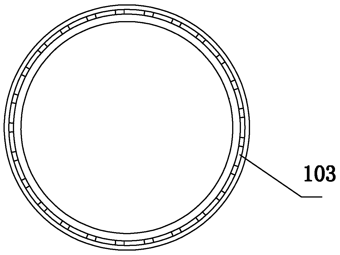
[0043] Figure 1 to Figure 9 As shown, a cage and steel ball assembly assembly mold is used for the assembly of cage 1 and steel ball 2, and specifically relates to the assembly of cage 1 and steel ball 2 components of thin-walled angular contact ball bearings for high-end bicycle racing headsets mold; such as Picture 1-1 , Figure 1-2 As shown, the cage and steel ball assembly includes a cage 1 and 25 steel balls 2; the cage 1 is in the shape of a ring, including a large ring 101 at the bottom, a small ring 102 at the top, and evenly distributed in the middle 25 steel ball pockets 103, the number of steel ball pockets 103 and the steel balls 2 are equal and the size matches;

[0044] like Figure 2-1 to Figure 2-4 As shown, the upper mold 3 and the lower mold 4 are included, the upper mold 3 and the lower mold 4 are generally circular, and the outer diameters of the upper mold 3 and the lower mold 4 are equal in size and larger than the outer diameter of the cage 1; The m...

Embodiment 2

[0059] Figure 1 to Figure 3-2 ,and Figure 5 , Image 6 and Figure 10 As shown, a cage and steel ball assembly assembly mold and its assembly method, the cage 1 is a soft nylon P16 cage. The cage 1 and steel ball 2 assembly includes 30 steel balls 2, 30 steel ball pockets 103 are evenly distributed in the middle of the cage 1, the diameter φ1 of the large ring 101 at the bottom of the cage 1 is 47.8mm, and the cage 1 The diameter φ2 of the upper small ring 102 is 45.5 mm, the height h of the cage 1 is 4.0 mm, and the diameter of the steel ball 2 is 3.175 mm.

[0060] The rest are the same as embodiment 1.


PUM


Abstract

The invention relates to a retainer and steel ball assembly assembling mold and an assembling method thereof. A retainer and steel ball assembly comprises a retainer and 15 to 50 steel balls; the retainer is annular and comprises a large ring at the bottom, a small ring at the upper portion and 15 to 50 steel ball pockets evenly distributed at the middle portion, and the steel ball pockets and thesteel balls are equal in number and matched in size; the retainer and steel ball assembly assembling mold comprises an upper mold and a lower mold, each of the upper mold and the lower mold is roundin the whole, and the outer diameters of the upper mold and the lower mold are equal and are larger than the outer diameter of the retainer; the upper mold includes a circular cover body at the upperportion and an annular lower convex ring at the lower portion, and the inner side face of the annular lower convex ring is used for press fit of the steel balls when the retainer and the steel balls are assembled; the lower mold comprises an annular mold body and a central hole, and the upper part of the annular mold body is sequentially provided with an annular inner convex ring, a steel ball press-fit groove and an annular upper convex ring from the inner side to the outer side; and a retainer containing groove is downwards arranged at the position, close to the outer side, of the bottom ofthe steel ball press-fit groove. The retainer and steel ball assembly assembling mold and the assembly method have the beneficial effects that the ball filling manner is a manner of filling multiple balls, the production efficiency is high, and safety is achieved.

Description

technical field [0001] The invention relates to a part assembly mold and an assembly method thereof, in particular to an assembly mold for a cage and a steel ball component assembly of a thin-walled angular contact ball bearing for a high-end bicycle race car. This product is an angular Practical technology for loading contact ball bearings. Background technique [0002] The assembly method of angular contact ball bearings is: first put the steel balls into the special nylon cage, and then put the steel balls and the cage into the bearing. The ball filling method of the original assembly into the cage is to manually fill the steel balls one by one into the ball pocket of the nylon cage. The number of balls in each cage is large, and 25 balls and 30 balls are commonly used. The production efficiency is low, and the manual operation without interval for several hours makes the operator's fingers very easy to be injured, and cannot engage in some work for a long time. Therefor...

Claims


Application Information

Patent Timeline
Patent Type & Authority Applications(China)
IPC IPC(8): F16C43/06
Inventor 马松苗
Owner 余姚市新丰轴承有限公司
Learn More